Related Industries
Curation by industry experts
Hot Articles
Popular Tags
Will Higher Rack Density Require a Switchgear Upgrade?
Will higher rack density require a switchgear upgrade? Not necessarily, but the answer depends on more than the power rating of a new AI rack.
Operators need to assess electrical capacity, peak demand, protection settings, redundancy, and equipment condition. Upgrade lead times can also determine when an expansion becomes operational.
Start With the Decision: More Power or More Density?
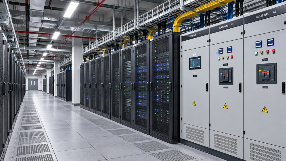
Higher density means more computing power concentrated in less space. It does not automatically mean the facility draws more electricity or needs new switchgear.
For example, replacing ten 10 kW racks with five 20 kW racks leaves the same nominal IT capacity. The electrical layout, however, may change substantially.
If the new deployment adds load instead of consolidating it, upstream equipment may have insufficient headroom. Cooling and supporting systems can increase the total demand further.
The distinction is important: a facility may have spare utility capacity but still need changes to a particular switchboard, breaker, feeder, busway, or protection scheme.
Conversely, an existing distribution path may accommodate the new racks if its ratings, operating limits, redundancy, and protection are verified under the proposed conditions.
Practical answer: a switchgear upgrade becomes necessary when the planned operating or failure conditions exceed a verified equipment limit that cannot be addressed acceptably otherwise.
Which Electrical Limits Could Trigger an Upgrade?
Switchgear is part of a chain extending from the utility connection through transformers, distribution equipment, UPS systems, and rack power distribution. Each link has separate limits.
Start with the actual single-line diagram and trace both normal and backup power paths to the proposed racks. Confirm that drawings match installed equipment.
Continuous current capacity. Check the relevant bus, breaker, cable, and termination ratings against expected sustained load, including applicable derating and manufacturer instructions.
Ratings on a nameplate are not always usable under site conditions. Ambient temperature, enclosure ventilation, altitude, installation arrangements, and local requirements can reduce permissible loading.
Peak and transient behavior. AI workloads can vary significantly. Review measured or vendor-provided load profiles, startup behavior, and the duration of demand peaks.
A short peak and a sustained overload do not have identical thermal effects. Engineers must evaluate their duration against equipment ratings and protective device characteristics.
Interrupting and withstand ratings. Existing equipment must be suitable for the available fault current. Transformer changes or additional sources can alter that fault current.
Check breaker interrupting capability and equipment short-circuit withstand ratings against an updated fault study. More load alone does not necessarily increase available fault current.
Protection and coordination. Higher loads may require revised breaker settings or equipment changes. Protective devices must still clear faults and coordinate with downstream devices.
A setting that avoids nuisance trips is not sufficient if it compromises cable protection, selective coordination, or required arc-flash performance. Changes need engineering review.
Physical capacity. A switchboard may have adequate bus capacity but no suitable spare breaker position. Adding a feeder can require an extension or replacement.
Condition and supportability. Obsolete breakers, unavailable spare parts, signs of overheating, or maintenance restrictions can make replacement prudent even when calculated capacity appears adequate.
How Much Capacity Do the New Racks Actually Need?
Do not treat rack nameplate power, average IT consumption, peak demand, and electrical design capacity as interchangeable. Each answers a different engineering question.
Obtain the proposed rack configuration, power supply arrangement, expected workload, measured operating profiles where available, and the vendor's documented maximum input requirements.
Then agree on a defensible design load and demand assumptions with the equipment supplier and electrical engineer. Avoid relying solely on unverified utilization forecasts.
For a simple illustration, ten additional 80 kW racks represent 800 kW of nominal rack input capacity. Their actual demand depends on configuration and workload.
That figure is not the complete facility increase. Add the incremental demand of cooling equipment and other supporting loads, using the proposed operating conditions.
For example, if engineering estimates 160 kW of additional cooling and support demand at the relevant operating point, the illustrative facility increase is 960 kW.
This is a planning example, not a universal cooling allowance. Liquid temperature, heat rejection, equipment efficiency, weather, and redundancy arrangements can change auxiliary demand materially.
At the same time, existing racks may be retired. Subtract removed loads only when the retirement schedule and electrical paths are confirmed and enforceable.
Calculate loading separately for each affected distribution path. Spare capacity on one board cannot automatically serve another without suitable interconnections, transfer arrangements, and engineering approval.
Convert power to current using the actual system voltage, phase arrangement, and expected power factor. Check phase balance and applicable harmonic effects where relevant.
Can the System Still Support the Load During a Failure?
Normal operating headroom is only the starting point. A facility designed for equipment failure or maintenance must also meet its chosen resilience requirements.
In an N+1 arrangement, examine what happens when the largest relevant component is unavailable. The remaining equipment must support the resulting load within its limits.
For dual-path racks, identify how power is shared normally and what each path must carry after a failure. Do not assume permanent 50% sharing.
A path that appears lightly loaded in normal operation may be unable to carry the full transferred load. This can make an upgrade necessary.
Check transfer logic, UPS operating modes, generator capacity, and downstream distribution together. A resilient switchgear design does not compensate for an overloaded transformer or UPS.
Maintenance scenarios matter too. Engineers should model planned isolation, temporary configurations, and credible failures according to the site's operating procedures and reliability objectives.
Where contractual availability requirements apply, review whether a proposed workaround changes maintenance exposure or fault tolerance. Lower capital expenditure may introduce unacceptable operational risk.
When Can Operators Avoid Replacing Switchgear?
Replacement is not the only response to a capacity constraint. The appropriate alternative depends on the limiting component, site topology, and resilience requirements.
Redistribute loads. Moving suitable loads between existing distribution paths may release capacity, provided cables, breakers, transfer behavior, and operating procedures support the change.
Retire equipment. Removing inefficient or underused systems can offset additional demand. Verify that the released capacity exists on the electrical path serving new racks.
Use an approved spare position. A suitable spare breaker space may allow a new feeder without replacing the entire assembly, subject to manufacturer compatibility.
Expand a supported lineup. Some equipment can accept an extension section, but its bus rating, fault rating, footprint, clearances, and outage requirements need verification.
Phase deployment. Bringing racks online in stages can align compute growth with electrical work. Each phase still needs adequate capacity and an approved operating envelope.
Apply power limits. Hardware or software caps can reduce demand if they are enforceable, monitored, and compatible with performance requirements and applicable design rules.
Power capping should not be assumed to override equipment ratings or code requirements. Evaluate what happens if controls fail, settings change, or communications are lost.
Any alternative should be compared with replacement on lifecycle cost, implementation time, maintenance exposure, and the risk of constraining future compute growth.
What Should the Engineering Assessment Include?
A useful assessment produces a documented decision for each affected electrical path, not simply a facility-wide statement that spare megawatts are available.
1. Establish the baseline. Collect current single-line diagrams, equipment schedules, nameplates, maintenance records, recent studies, and evidence of actual operating configurations.
2. Measure existing demand. Review sufficiently granular meter data across representative workloads and operating conditions. Identify peaks, sustained loads, and gaps in monitoring coverage.
3. Define the future load. Include rack demand, incremental cooling, deployment phases, retired equipment, and the expected location of each load.
4. Model operating scenarios. Calculate normal, peak, failure, transfer, and maintenance conditions against the facility's documented redundancy and availability requirements.
5. Update electrical studies. As applicable, review load flow, short circuit, protection coordination, and arc-flash analysis using current equipment and source data.
6. Inspect physical constraints. Confirm available breaker positions, cable routes, access clearances, ventilation, equipment condition, and the feasibility of planned installation work.
7. Record the decision. Identify limiting components, assumptions, required modifications, owners, acceptance criteria, and unresolved risks before committing to a deployment date.
Qualified electrical engineers and site operations personnel should review the results against the applicable jurisdiction, equipment instructions, and facility standards. Calculations alone are insufficient.
How Do Lead Times and Outages Affect the Business Case?
A switchgear project includes more than equipment procurement. Design, manufacturer approval, permits, installation, protection testing, commissioning, and operational handover all affect the schedule.
Delivery times vary by specification, supplier, region, and market conditions. Obtain current written quotations rather than treating a generic lead-time estimate as a commitment.
Ask suppliers to identify drawing approval milestones, manufacturing slots, testing scope, shipping assumptions, spare parts, and conditions that could change the promised delivery date.
Existing equipment modifications may require a planned outage. For operating data centers, the availability of that outage window can matter as much as delivery.
Compare options using installed cost and timing, including temporary power, commissioning, engineering, maintenance, and potential lost compute revenue from delayed deployment.
Also account for the cost of constrained operation. A cheaper interim solution may limit rack utilization or require additional monitoring and manual intervention.
Before purchase, define acceptance tests for protective devices, controls, transfer sequences, communications, and the relevant operating scenarios. Assign responsibility for resolving failed tests.
Track capacity through clear milestones: utility allocation, connection, installed equipment, commissioning, and capacity actually available to IT. These are not equivalent project states.
Questions to Ask Before Approving the Deployment
Ask the electrical engineer which specific component limits the proposed load, under which operating scenario, and how much verified headroom remains after the change.
Ask the rack supplier for input power profiles, power cap behavior, startup characteristics, and documentation showing how redundant power supplies behave during a feed failure.
Ask operations whether the proposed configuration can be maintained without breaching availability commitments, and whether staff have the procedures and training to operate it.
Ask the switchgear manufacturer whether proposed breakers, extensions, or settings are compatible with the installed assembly and supported for its remaining service life.
Ask procurement for a complete schedule and cost comparison, including installation, outage dependencies, testing, supplier support, and the consequences of a delayed delivery.
Conclusion: Upgrade the Constraint, Not the Rack Density
Higher rack density requires a switchgear upgrade only when the proposed deployment exceeds a verified capacity, protection, physical, condition, or resilience limit.
The decision begins with measured load and a credible future demand profile, then follows every affected power path through normal operation, failure, and maintenance.
Where limits are exceeded, compare redistribution, retirement, approved expansion, phased deployment, and replacement against reliability requirements and the full project schedule.
The result should be a documented engineering decision that connects available electrical capacity to the compute deployment the facility can actually commission and operate.
Questions about data center smoke detection standards? Contact RackLedger for further insights.
We respect your privacy. Your information is strictly confidential.
Recommended News
 How Automatic Reclosers Restore Power After Transient Line FaultsAutomatic Reclosers restore power after temporary line faults. Discover how reclosing sequences, protection settings, and lockout support grid reliability.Nov 04, 2026
 Why Transformer Cooling Fans Fail and How to Diagnose Common FaultsTransformer Cooling Fans not working as expected? Learn how to diagnose common faults, check airflow and controls, and restore reliable cooling safely.Nov 04, 2026
 What Is Transformer Oil? Insulation and Cooling Functions ExplainedTransformer oil supports electrical insulation and cooling. Discover how it works, how it is tested, and why its condition matters for power reliability.Nov 04, 2026
 Sodium-Ion UPS Batteries vs. Lithium-Ion: What Buyers Should CompareSodium-Ion UPS Batteries vs. lithium-ion: compare runtime, safety, compatibility and lifecycle costs to make a confident data center buying decision.Nov 04, 2026