Related Industries
Curation by industry experts
Hot Articles
Popular Tags
How Do I Verify Current Transformer Readings After a Retrofit?
How do I verify current transformer readings after a retrofit? Start by checking that the installed CT ratio, orientation, wiring, and meter configuration match the updated electrical system. Then compare readings with a suitably rated reference instrument under known operating conditions, accounting for load variation and measurement accuracy. For data center operators and facility engineers, documenting these checks can help identify configuration errors before they affect power monitoring, capacity planning, or protection.
The most useful comparison is not simply “the two numbers are close.” It establishes that both instruments measure the same conductor, at the same time, using compatible measurement methods. A convincing display can still be wrong if the CT is assigned to the wrong phase or the monitoring software applies an incorrect scaling factor.
Start with the electrical system as it exists today
A retrofit can change more than the CT itself. A new meter, replacement switchgear, revised feeder arrangement, additional parallel conductors, or a change in the monitoring system can all affect what a reading represents. Before testing, compare the as-built single-line diagram, wiring drawings, CT nameplates, meter settings, and commissioning records with the equipment actually installed.
Identify the measurement boundary. Is the CT monitoring a utility incomer, UPS output, power distribution unit, busway, or individual branch? A reading on an upstream feeder should not be expected to match a downstream IT-load meter exactly: the two points may include different equipment, losses, or loads. Where capacity decisions depend on the result, record the boundary alongside the number.
Check whether the CT is intended for metering, protection, or both. These uses can require different accuracy characteristics and burden capabilities. A meter comparison at normal load does not establish that a protection CT will behave correctly during a fault.
Put safety and test authority before access
CT verification can involve hazardous electrical equipment. Inspection, isolation, testing, and any wiring changes should be performed by qualified personnel under the site’s electrical safety procedures and applicable local requirements. Plan switching and access with operations staff, particularly where a test could affect live data center loads or redundancy.
Never open-circuit the secondary of an energized conventional current-output CT. Dangerous voltage can develop across the open circuit. Use the approved shorting and isolation arrangements and the manufacturer’s procedures before disconnecting or testing secondary wiring. Do not assume that a voltage-output sensor, Rogowski coil, or other nonconventional device follows the same secondary handling rules; identify the device and follow its instructions.
A clamp comparison may be possible without disturbing the secondary, but it is not automatically safe. The test point must be accessible under the site’s approved work plan, and the instrument and accessories must be suitable for the voltage environment, available fault conditions, current range, and intended measurement.
Check the ratio, installation, and signal path
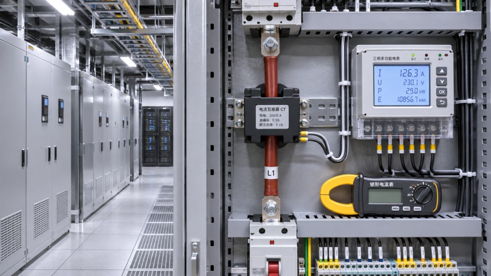
A CT ratio describes the relationship between primary current and its rated secondary output. For example, an ideal 1,000:5 current-output CT produces 1 A on its secondary when 200 A flows in the primary. The meter must be configured for the actual ratio and input type. If a replacement CT has a different ratio but the old setting remains, the displayed current can be consistently high or low even when the wiring is intact.
Trace the full signal path rather than checking the meter alone. A building management system, power monitoring platform, gateway, or register map may apply its own multiplier. Confirm where scaling occurs and whether the value presented to operators has been scaled once, twice, or not at all. Compare the meter’s local display with the corresponding software point, including units and update interval.
Installation details deserve equal attention:
- Confirm that each CT surrounds the intended phase conductors and that parallel conductors are included as designed. An omitted parallel cable can leave a plausible but understated reading.
- Check CT direction and secondary polarity against the drawings and meter instructions. A reversed CT may still show a plausible current magnitude while producing incorrect power direction, power factor, or energy readings.
- Verify that CT inputs and voltage references correspond to the same phases. A phase mismatch can distort calculated power even when individual current readings look reasonable.
- Inspect accessible wiring, terminal identification, and shorting links under the approved procedure. A closed shorting link left in the wrong position, a loose connection, or a wiring error can invalidate the measurement.
For split-core CTs, follow the manufacturer’s closure and mounting requirements. A poorly seated core can affect performance. Also check that the connected meter and wiring do not exceed the CT’s specified burden; excessive burden can contribute to inaccurate measurement, especially as operating conditions change.
Compare each phase with an independent reference
Use a reference instrument with current range, accuracy, frequency response, and waveform capability appropriate to the circuit. A true-RMS instrument is generally relevant for loads with distorted waveforms, but the instrument’s specified bandwidth and crest-factor limits still matter. Data center power supplies, UPS equipment, and variable-speed drives can produce waveforms that are not well represented by a basic instrument under every operating condition.
Measure each phase at an approved point on the same electrical section monitored by the installed CT. Record the reference and installed-meter values as nearly simultaneously as practical. If the load changes rapidly, use synchronized logging or compare matching time averages rather than a momentary clamp reading against a delayed dashboard value.
With parallel conductors, check the conductor arrangement carefully. A clamp around only one cable does not necessarily measure the entire phase current. Summing separately measured RMS magnitudes is not always reliable if currents have different phase relationships or waveforms; use an engineered measurement method suitable for the installation. Never place a clamp around multiple phase conductors and assume it reports total load current.
Where operating conditions allow, repeat the comparison at more than one representative load. A single low-current check may be dominated by instrument resolution or low-end accuracy. A check during normal loading is more useful for everyday monitoring, while another approved operating point can help reveal errors that vary with current. Do not deliberately alter critical loads without an authorized test plan.
Decide what counts as agreement before testing
Set acceptance criteria in the commissioning plan using the project requirements and the relevant specifications for the CT, meter, reference instrument, and measurement conditions. A CT accuracy class alone is not necessarily the allowable difference between two complete measurement systems. Resolution, calibration uncertainty, burden, waveform distortion, temperature, and timing can all affect the comparison.
For a simple comparison, calculate the difference as the installed reading minus the reference reading, divided by the reference reading, then multiply by 100. This expresses the deviation relative to the reference; it does not prove the reference is exact. At very low currents, an absolute difference may be more informative than a percentage.
Use power readings to find errors that current alone misses
A CT can report the right magnitude while the meter calculates the wrong real power. Once phase currents are checked, review phase voltages, phase relationships, power factor, and the sign of real power against the expected operating condition. Unexpected import or export indications, or a power factor inconsistent with the connected load, warrant investigation of polarity, phase assignment, and voltage wiring.
Interpret these values in context. Some equipment can legitimately produce unusual power-factor or direction readings during particular operating states. Use a suitable power analyzer and the equipment documentation where needed; do not reverse wiring merely to make a display look more familiar.
For protection circuits, commissioning may also require ratio, polarity, insulation, excitation, burden, relay-setting, or injection tests as specified by the protection engineer and equipment manufacturer. Primary injection can exercise a wider part of the measurement chain, while secondary injection checks downstream circuits but does not by itself verify the CT’s primary measurement. Neither should be treated as a substitute for the project’s protection test plan.
When the numbers disagree, follow the pattern
A similar proportional error on all three phases points toward a shared configuration issue, such as an incorrect ratio or software multiplier. An error on one phase suggests a phase-specific problem: CT placement, input assignment, wiring, or the reference measurement itself. A reading that changes disproportionately with load may require closer examination of burden, CT selection, core closure, waveform, or measurement range.
These are diagnostic leads, not proofs. Before changing settings, rule out different measurement boundaries, unsynchronized samples, and reference-instrument limitations. Record the original configuration, obtain the necessary approval, make one controlled change at a time, and repeat the relevant tests. If the issue affects protection or cannot be resolved safely, escalate it to the responsible engineer or equipment supplier.
Leave an evidence trail operators can use
The handover should identify the circuit and measurement boundary, CT make and ratio, phase assignments, meter settings, software scaling, reference instrument and calibration status, test date, load conditions, readings, acceptance criteria, and any unresolved deviations. Include updated drawings and a record of who approved the results. Where monitoring and protection share dependencies, state which functions were tested and which were outside the scope.
This distinction matters when readings feed capacity plans or efficiency reporting. An accurate feeder current is not automatically IT load, and an instantaneous current is not a peak-demand study. RackLedger’s proposed coverage of data center power infrastructure emphasizes those boundaries because a number is only useful when its operating context is clear. Before relying on a retrofitted meter for expansion decisions, confirm both that the measurement chain passed its checks and that it measures the load the decision actually concerns.
Questions about data center smoke detection standards? Contact RackLedger for further insights.
We respect your privacy. Your information is strictly confidential.
Recommended News
 How Automatic Reclosers Restore Power After Transient Line FaultsAutomatic Reclosers restore power after temporary line faults. Discover how reclosing sequences, protection settings, and lockout support grid reliability.Nov 04, 2026
 Why Transformer Cooling Fans Fail and How to Diagnose Common FaultsTransformer Cooling Fans not working as expected? Learn how to diagnose common faults, check airflow and controls, and restore reliable cooling safely.Nov 04, 2026
 What Is Transformer Oil? Insulation and Cooling Functions ExplainedTransformer oil supports electrical insulation and cooling. Discover how it works, how it is tested, and why its condition matters for power reliability.Nov 04, 2026
 Sodium-Ion UPS Batteries vs. Lithium-Ion: What Buyers Should CompareSodium-Ion UPS Batteries vs. lithium-ion: compare runtime, safety, compatibility and lifecycle costs to make a confident data center buying decision.Nov 04, 2026