Related Industries
Curation by industry experts
Hot Articles
Popular Tags
Optical Transceivers for Data Centers: Reach, Speed and Compatibility
The right optical transceiver is not simply the fastest module that fits a switch port. It must support the required Ethernet rate and physical interface at both ends, operate over the installed cabling within its optical limits, and be accepted by the host equipment. A mismatch in any one of those areas can turn an inexpensive purchase into a link that will not come up or cannot run reliably.
Start with the link, not the module catalog: identify the two devices, the port configuration, the cable route and the operating requirements. Then compare the available optical interfaces against those conditions. This approach also makes it easier to decide when a direct-attach copper cable or active optical cable is a better fit than separate pluggable optics.
Match the interface to the link, not just the distance
Optical transceivers are specified for particular combinations of data rate, optical signaling, fiber type and reach. Two modules with the same advertised speed can use different numbers of fibers, wavelengths or optical lanes. They are not necessarily interchangeable, even when their connectors look similar.
Reach is a starting point for narrowing the options. It is not a guarantee that every link shorter than the published maximum will work. The stated distance normally assumes a defined fiber type and channel loss. Patch panels, connectors, splices and the condition of the installed cable all affect how much optical power reaches the far end.
These are selection directions, not universal rules. A short route may still favor single-mode fiber when that is the installed plant or when the organization wants a consistent cabling design. A longer-reach optic may be appropriate for an unusual loss budget, but its receiver limits must still be respected on a short, low-loss connection.
Read speed as a complete port configuration
The rate printed on a module describes the aggregate interface, not necessarily the rate of each electrical or optical lane. A high-speed port can use several lanes together, and some ports can divide those lanes into multiple lower-speed connections. That capability depends on the switch or network adapter, its software and the particular module or cable.
For example, a port advertised at a high aggregate rate may offer a breakout mode, but that does not mean every module of the same form factor supports that mode. The remote devices must also support the resulting rates and compatible physical interfaces. Check whether enabling breakout affects neighboring ports or requires a configuration change before ordering.
Form factors such as SFP, QSFP and their variants describe module families and physical interfaces. They are useful filters, but they do not by themselves establish interoperability. A module that fits mechanically may still use an unsupported electrical interface, exceed the port's power allowance or require a software version that is not installed.
Include forward error correction in the review. FEC helps a link tolerate a defined level of transmission error, but both ends need compatible settings and support. A link that appears physically sound can remain down, or show errors, when FEC configuration does not match the interface requirements.
Work from the installed fiber and the actual loss budget
Multimode fiber is commonly used for shorter data center links; single-mode fiber supports a range of interfaces, including options intended for longer paths. The terms do not describe interchangeable media. A multimode optic and a single-mode optic cannot be paired simply because they operate at the same Ethernet rate.
For an existing route, obtain the fiber type and measured channel length from the cabling records, then account for the actual path through panels and cross-connects. Multimode reach depends on both the optic and the installed fiber grade. A module's reach on one grade must not be assumed for another.
The optical loss budget is the amount of signal attenuation the transmitter and receiver can tolerate for a defined interface. Compare it with the total channel loss, including fiber, connectors, splices and any planned additions. Leave an engineering margin for aging, repairs and measurement uncertainty rather than designing exactly to the limit.
Also check the receiver's maximum input power. On some short links using longer-reach optics, too much received power can be a problem. An attenuator may be appropriate when the link design calls for one; adding one without calculating the power levels can instead push the signal below the receiver's usable range.
Connector shape is not the whole connection
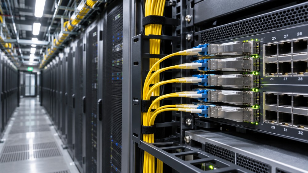
Duplex connectors and multi-fiber connectors serve different cabling arrangements. Multi-fiber links also require the correct fiber count, polarity and mapping through every patch panel and trunk. A cable can physically connect at both ends while transmit and receive paths land on the wrong fibers.
When planning a breakout, document the path from each host lane to its destination port. Include patch cords, adapters and trunk polarity in the drawing. This is especially useful when the installation combines existing structured cabling with new high-speed equipment.
Separate optical interoperability from host compatibility
There are two distinct compatibility questions: can the modules communicate across the fiber, and will each host accept and operate its installed module? Passing one test does not answer the other.
At the optical layer, compare the full interface specification at both ends: data rate, signaling, wavelength arrangement, fiber type, connector, reach and any required FEC. Modules do not have to carry the same equipment-vendor label to communicate, but they do need compatible physical interfaces and link budgets. Matching only the speed or wavelength is not enough.
At the host layer, check the exact switch or adapter model, port type, software release and supported module part number. Equipment may restrict certain modules, report them as unsupported or provide limited diagnostics. Power class and thermal limits matter too: a module that works in one port or chassis may not be approved for another.
Third-party optics can offer sourcing flexibility, but their evaluation should include more than whether the link initially comes up. Agree on support responsibilities, replacement arrangements and escalation between the equipment and module suppliers. Test representative units in the intended hardware and software environment, including any monitoring and failure-handling functions the operations team relies on.
Choose between pluggable optics, active cables and copper
Direct-attach copper cables can be a practical choice for short, predictable routes. They avoid separate optical modules and fiber patch cords, but cable thickness, bend radius, supported length and port compatibility can constrain dense rack layouts. They are less suitable where the route exceeds the supported reach or where cable management makes installation difficult.
Active optical cables integrate optical components with the cable. They can simplify some short-to-medium connections and reduce the number of separate parts, but the assembly is generally replaced as a unit. Fixed cable length and routing constraints matter when equipment is moved or when a cable passes through established pathways.
Pluggable transceivers with separate fiber offer more flexibility when the cabling plant is already installed or when modules and patch leads need to be replaced independently. That flexibility brings more interfaces to manage: optics, fiber type, connectors, polarity and link cleanliness all become part of the operating process.
Compare the whole connection rather than the module price alone. Include both endpoints, patch cords or cable assemblies, installation labor, testing, spares and the practical cost of replacing a failed component. For dense switch deployments, also compare module power and heat against the host's supported limits and the rack's cooling plan.
Specify acceptance before placing the order
A useful procurement specification describes each link as a system. Record the device models and software, required port rate, optical interface, fiber route, connector and polarity, measured or designed channel loss, and any breakout or FEC settings. State the acceptable module part numbers or the interoperability and host-support requirements that alternatives must meet.
For a representative installation, acceptance should cover more than a link-up indicator:
- Confirm that both hosts recognize the modules and report the expected port speed and configuration.
- Inspect and clean fiber connectors using the site's established procedures before connection and measurement.
- Measure the channel and review transmitted and received optical power against the interface's operating limits.
- Run traffic representative of the intended service and check error counters, including FEC statistics where available.
- Test monitoring, alarm reporting and replacement procedures, and record the module identifiers and results.
Digital optical monitoring is useful for troubleshooting, but reported values should be interpreted within the module's specified accuracy and the equipment's diagnostics. An optical power reading alone does not prove that a link will perform correctly under load.
For an initial deployment, reserve time to test the complete path before ordering for every port. A validated combination of host, module, cable plant and configuration is a stronger basis for purchasing and spares planning than a list of modules that happen to share the same advertised speed.
Questions about data center smoke detection standards? Contact RackLedger for further insights.
We respect your privacy. Your information is strictly confidential.
Recommended News
 Choosing Server Rack Vibration Dampers for Sensitive IT EquipmentChoose Server Rack Vibration Dampers with confidence. Explore load, frequency, anchoring, and supplier criteria for sensitive IT equipment.Nov 04, 2026
 How rack power density affects prefabricated data center rack capacityDiscover how rack power density affects prefabricated data center rack capacity, and learn to assess power, cooling, redundancy, and layout limits.Nov 04, 2026
 Server Chassis Airflow: Why Hot Spots Form and How to Fix ThemServer Chassis hot spots can develop even in cool data centers. Discover how to trace airflow issues, fix common causes, and verify cooling performance.Nov 04, 2026
 Choosing Server Rack Shelves: Load Capacity, Depth and MountingServer Rack Shelves made simple: compare load capacity, usable depth and mounting options to choose a safe, compatible shelf with confidence.Nov 04, 2026