Related Industries
Curation by industry experts
Hot Articles
Popular Tags
How rack power density affects prefabricated data center rack capacity
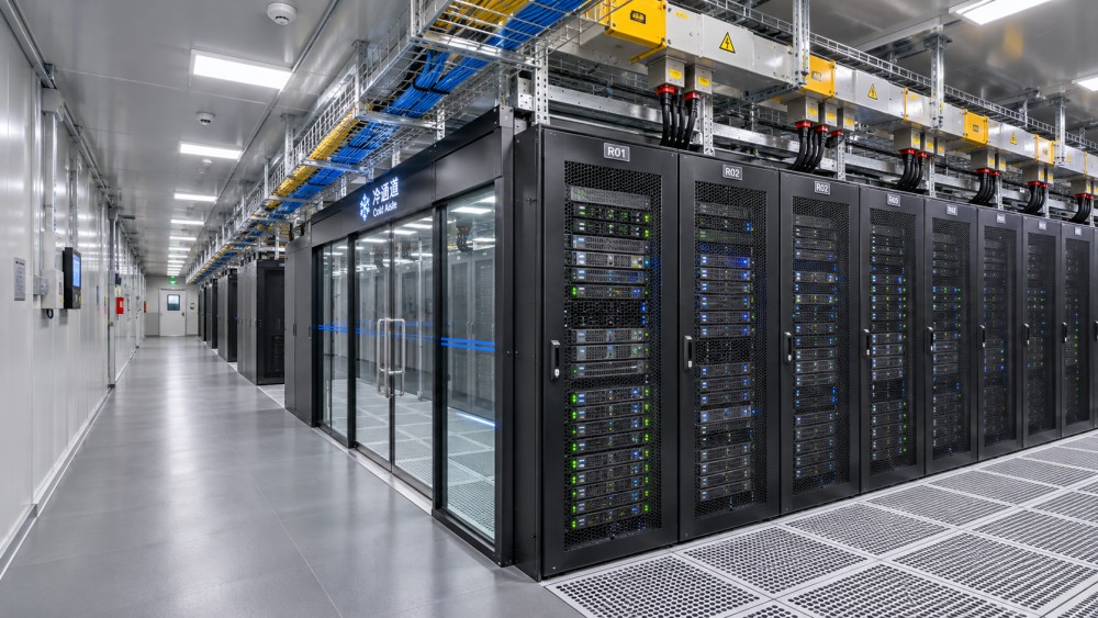
A prefabricated data center rated for a certain number of racks cannot necessarily support that number at every rack power density. The usable count is bounded by the power and cooling available under the required operating and redundancy conditions, as well as by rack placement, floor loading, cabling and service access.
A module advertised as supporting 20 racks at 10 kW each has a different capacity profile from one supporting four racks at 50 kW each, even though both configurations represent 200 kW of IT load. The second arrangement concentrates electrical current and heat into fewer locations. Whether it works depends on the distribution and cooling systems serving those locations, not just the module’s aggregate rating.
Rack count is not the same as usable IT capacity
Rack power density is the electrical load assigned to an individual rack, expressed in kilowatts per rack. Prefabricated data center rack capacity can describe several different things: the number of cabinets that physically fit, the number that can be supplied at a stated load, or the number that can remain operational after a specified equipment failure. Those figures should not be treated as interchangeable.
For an initial estimate with uniform rack loads, divide usable IT power by the design load per rack. Repeat the calculation using usable cooling capacity at the relevant operating conditions. The lower result is an approximate upper limit before checking individual power paths, cooling distribution and physical constraints:
Indicative powered rack count = the lower of (usable IT power ÷ design kW per rack) and (usable cooling capacity ÷ design kW of heat per rack).
The result must be rounded down to a whole rack and then checked against the cabinet positions and infrastructure actually available. The calculation also assumes that essentially all IT electrical power becomes heat within the cooling boundary being assessed. It is not enough to compare nameplate ratings if part of the heat is removed through a separate liquid-cooling system or if cooling equipment serves other loads.
Consider a module with 200 kW of usable IT power and 180 kW of usable IT heat-removal capacity, both available under the intended operating condition. At a uniform design load of 10 kW per rack, cooling limits the initial estimate to 18 racks. At 30 kW per rack, the same arithmetic gives six racks. Neither figure proves that those racks can be deployed: branch-circuit ratings, cooling delivery and cabinet positions could lower the final count.
“Usable” is doing important work in this calculation. Utility supply, facility input power, UPS output, rack power distribution and IT equipment input are different measurement boundaries. A module with a 200 kW facility electrical connection does not automatically have 200 kW available to IT equipment; cooling, power conversion losses and other facility loads also consume power.
Electrical limits move from the module to the rack
As density rises, the total IT load can remain unchanged while individual distribution components must carry more current. A module may have adequate aggregate UPS capacity but lack sufficiently rated busway tap-offs, panel circuits, rack power distribution units, connectors or cables for a proposed high-density cabinet.
The applicable current depends on voltage, phase configuration, power factor and the load distribution across phases. Designers also need to apply the governing electrical code and equipment ratings, including relevant continuous-load requirements, conductor sizing, protection and environmental derating. A kW-per-rack figure alone does not establish that the complete circuit is suitable.
Redundancy changes the calculation. In a dual-fed arrangement, the critical question is not simply how much load each feed carries during normal operation, but whether the surviving path can carry the required load after the other path fails or is taken out of service. Sharing 30 kW between two feeds in normal operation does not establish that either feed can support 30 kW on its own.
The same distinction applies upstream. A UPS system described as redundant may have sufficient installed nameplate capacity while offering less usable capacity under the specified failure or maintenance condition. Capacity claims should identify the protected load, the failure scenario and any permitted load shedding. A design that maintains only selected racks after a failure is not equivalent to one that maintains the entire installed IT load.
Cooling capacity must reach the concentrated load
Cooling is constrained by both total heat rejection and the ability to deliver cooling to each rack. A module can have enough aggregate cooling on paper while a high-density rack exceeds the airflow, temperature or liquid-flow capacity at its assigned position.
With air cooling, heat removal depends on airflow through the IT equipment and the temperature rise across it. Higher rack loads require enough supply air at acceptable inlet conditions and an effective return path for hot air. Containment, blanking panels, cable openings and equipment arrangement affect whether supply and return air mix. A room-level cooling rating does not by itself demonstrate acceptable inlet temperatures at every server.
Liquid cooling changes where heat is removed, but it does not eliminate the need to account for the full load. In direct-to-chip systems, some heat is transferred to liquid while other components and losses still discharge heat to air. The split depends on the IT equipment and cooling design; it should come from configuration-specific information rather than a generic percentage.
The liquid path must be assessed from the rack connections through the coolant distribution unit, heat exchangers and facility heat-rejection system. Flow, pressure drop, supply temperature, water quality and controls all affect the supported load. A rack-level rating is meaningful only when the stated facility-side conditions can be maintained at the design load, including during relevant maintenance and failure scenarios.
Liquid-cooling auxiliaries also need a clear accounting boundary. Pumps and controls can add electrical demand and heat. If their consumption is included in facility power rather than IT power, the capacity schedule should say so. Otherwise, a comparison can accidentally count the same allowance twice—or omit it entirely.
Average density can conceal an infeasible layout
A module’s average kW per rack is a planning ratio, not proof that every rack position has that capacity. For example, a 200 kW IT allocation across 20 cabinets averages 10 kW per cabinet. A layout containing several 30 kW racks may still fit within the total allocation, but only if the designated locations have the necessary electrical feeds, cooling interfaces and clearances.
The loading pattern matters as much as the arithmetic. Adjacent high-density racks can create a concentrated cooling and cable-routing demand that is different from the same racks separated across a module. Liquid-cooled positions may depend on manifold locations and hose routing, while air-cooled positions depend on the supply and return configuration. Spare aggregate capacity elsewhere in the module does not automatically solve a local constraint.
A useful capacity schedule therefore identifies each rack position or rack group, its maximum design load, supply path and cooling method. It should also distinguish positions that are physically reserved for future use from positions already equipped with power and cooling distribution. A vacant cabinet location is not necessarily a ready-to-use rack position.
Design load, peak demand and measured use answer different questions
Average metered consumption is useful for understanding utilization, but it is not necessarily an appropriate basis for sizing protective devices, standby capacity or cooling. Workload demand changes with hardware configuration, software behavior and operating state. A calculation based only on an observed average can leave insufficient margin for a simultaneous increase in load.
The design basis should state the assumed maximum demand, the averaging interval used for any peak figure, and whether power limiting is part of the operating strategy. Enforced rack or server power caps can make a higher installed hardware count compatible with a fixed infrastructure allocation, but only if the caps are configured, monitored and maintained as part of operations. The resulting capacity is conditional on that control, not the unconstrained equipment nameplate load.
Similarly, diversity—the assumption that all racks will not reach their maximum at the same time—can improve infrastructure utilization, but it is an engineering assumption rather than free capacity. Its validity depends on the workload, the population of equipment and the consequences if simultaneous demand exceeds the allocation. If the design relies on diversity, the response to an exceedance should be explicit: throttling, load shedding or another controlled action.
Physical capacity can become the binding constraint
Increasing rack density can reduce the number of cabinets needed for a given IT load, but the remaining cabinets may be heavier and more demanding to install and service. A module’s floor must support the actual loaded rack arrangement, including equipment, rack PDUs and relevant cooling components.
Floor checks should address more than a single average loading figure. Concentrated loads at casters or leveling feet, the module’s structural support arrangement and the route used to move equipment into position can all matter. Any external slab or support system also needs to be compatible with the delivered module and its operating loads.
High-density configurations can consume space outside the cabinet footprint. Power cables, overhead busway drops, liquid manifolds, hose bend radii and service loops must fit without obstructing airflow or maintenance. Door swing, equipment withdrawal and access to isolation points also affect whether a nominal rack position is usable. Installing the maximum number of cabinets in a drawing can leave too little space to replace equipment safely.
What the capacity rating should document
A defensible rating links a proposed rack layout to a defined operating condition. It should make clear which figures describe the prefabricated module alone and which depend on site-provided electrical supply, water or other heat-rejection infrastructure. Useful documentation includes:
- Load schedule: rack locations, design kW per position, expected peak demand, diversity assumptions and any enforced power limits.
- Electrical boundary: facility input and usable IT capacity, voltage and phase, distribution ratings, losses, redundancy and supported failure conditions.
- Cooling basis: air and liquid heat loads, design inlet or supply conditions, rack-level delivery limits, auxiliary loads and heat-rejection dependencies.
- Physical layout: cabinet dimensions and loaded weights, floor and support requirements, cable and pipe routes, and service clearances.
- Acceptance evidence: the load distribution, operating conditions and tests used to demonstrate capacity, including any agreed failure or maintenance scenarios.
Applicable standards and local codes can inform electrical safety, equipment installation and environmental conditions, but a general statement of compliance does not establish the supported rack count. The relevant edition, jurisdiction, system boundary and specific design assumptions must be identified in the project documentation.
The most useful capacity figure is therefore not the largest rack count or the highest individual kW rating. It is the number and distribution of racks that can receive the required power and cooling, within physical limits, under the operating and resilience conditions the deployment actually requires.
Questions about data center smoke detection standards? Contact RackLedger for further insights.
We respect your privacy. Your information is strictly confidential.
Recommended News
 Choosing Server Rack Vibration Dampers for Sensitive IT EquipmentChoose Server Rack Vibration Dampers with confidence. Explore load, frequency, anchoring, and supplier criteria for sensitive IT equipment.Nov 04, 2026
 How rack power density affects prefabricated data center rack capacityDiscover how rack power density affects prefabricated data center rack capacity, and learn to assess power, cooling, redundancy, and layout limits.Nov 04, 2026
 Server Chassis Airflow: Why Hot Spots Form and How to Fix ThemServer Chassis hot spots can develop even in cool data centers. Discover how to trace airflow issues, fix common causes, and verify cooling performance.Nov 04, 2026
 Choosing Server Rack Shelves: Load Capacity, Depth and MountingServer Rack Shelves made simple: compare load capacity, usable depth and mounting options to choose a safe, compatible shelf with confidence.Nov 04, 2026