Related Industries
Curation by industry experts
Hot Articles
Popular Tags
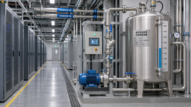
Coolant Reservoirs: Causes of Air Buildup in Liquid Cooling Loops
After a coolant refill or component replacement, a liquid cooling loop may develop pump noise, unstable flow or rising equipment temperatures. Air visible in Coolant Reservoirs is a useful diagnostic clue, but it does not by itself prove that the reservoir is leaking. Gas may have been left behind during filling, drawn in through a low-pressure connection, released from the coolant as pressure or temperature changed, or generated by a fault elsewhere in the loop.
Start by determining whether the bubbles are clearing after service or continue to return during stable operation. Check coolant level, pressure, flow and recent maintenance history together. Repeated bleeding without finding the source can mask a leak, introduce more contamination or leave a pump running with inadequate inlet pressure.
Read the symptoms before opening the loop
Small bubbles immediately after filling are not unusual: trapped pockets can move out of cold plates, hoses and high points as coolant circulates. The important distinction is the trend. A decreasing quantity of bubbles, with stable pressure and flow, calls for a different response from continuous foam, recurring air pockets or a level that keeps falling.
Record the operating state before changing anything: which pumps are running, coolant temperatures, indicated pressures, flow readings and reservoir level. Compare these with the equipment’s normal operating range and previous records, using readings taken under similar load and pump conditions. A level change between a cold, stopped system and a warm, running system may reflect expansion, pressure changes or coolant moving between components rather than a leak.
Noise alone is not proof of air ingestion. Cavitation, a restricted inlet, mechanical pump damage and vibration transmitted through piping can sound similar. Likewise, high temperature can result from insufficient flow, a heat exchanger issue or an inaccurate sensor. Treat bubbles as evidence to investigate, not as a complete diagnosis.
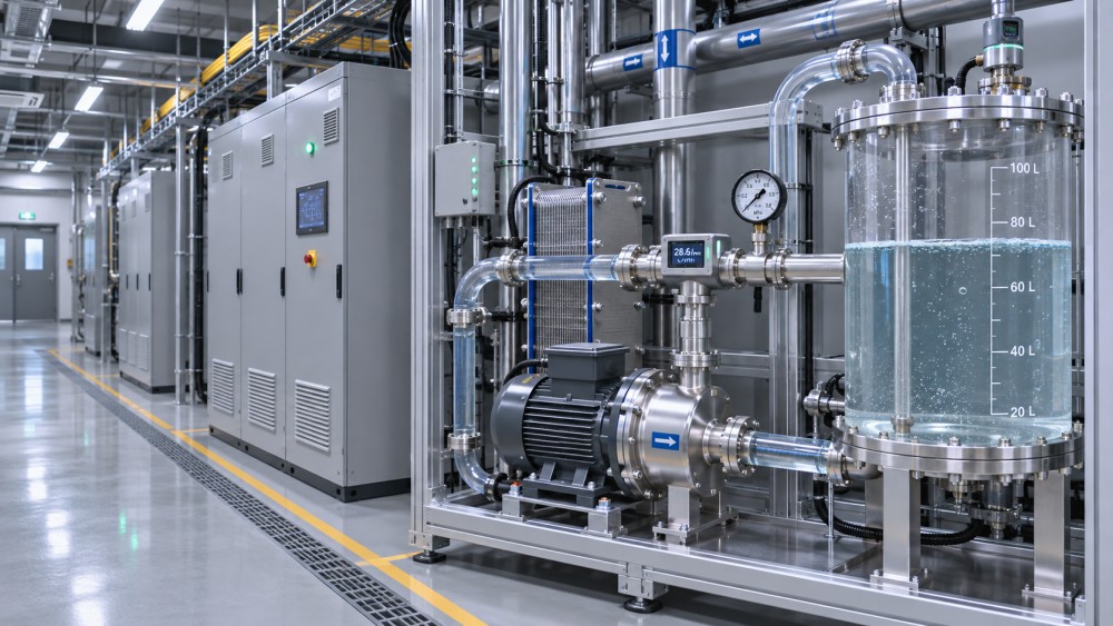
Where the gas may be coming from
Air left in the system after filling
High points, horizontal pipe runs, cold plates and branches with limited flow can hold pockets of air even when the reservoir appears full. A quick fill may wet the reservoir and main line while leaving a remote branch incompletely filled. Closed isolation valves, incorrect valve positions or an obstructed vent path can prevent air from reaching the designated bleed point.
Review the fill sequence and valve positions against the loop schematic. Pay particular attention to equipment recently installed, disconnected or drained. Use the manufacturer’s approved filling and venting procedure; some systems require a controlled fill rate, vacuum filling or a specific pump sequence. Do not assume that opening every available valve will purge the loop safely.
Air drawn in on the pump suction side
A joint can admit air without producing an obvious outward coolant leak when local pressure falls below atmospheric pressure. Potential locations include pump shaft seals, service connections, hose fittings and seals disturbed during maintenance. A low reservoir level or a restricted suction line can make the problem worse by lowering inlet pressure or allowing a vortex to carry surface air toward the outlet.
Inspect the suction path first when bubbles increase with pump operation or a particular pump speed. Look for loose or damaged fittings, failed seals, kinks, debris at strainers and signs of previous leakage. Pressure readings taken at the locations specified by the manufacturer can help establish whether the pump has adequate inlet conditions. Do not tighten a pressurized fitting blindly; isolate and depressurize the affected section before making a repair, following the site procedure.
Dissolved gas released from coolant
Coolant can contain dissolved gases that become visible when pressure decreases or temperature rises. Release is especially plausible near a pump inlet or another low-pressure region. This does not necessarily mean that outside air is entering, although persistent gas release still warrants investigation of pressure control, coolant condition and operating temperatures.
Compare bubble formation at different permitted operating states. Bubbles appearing mainly when pressure drops, without a continuing loss of coolant, may point toward gas coming out of solution. Confirm the interpretation against the system design and coolant supplier’s guidance; appearance alone cannot reliably distinguish released gas from air entering through a small leak.
A reservoir that cannot separate air effectively
A reservoir needs sufficient coolant level and an appropriate flow path to let entrained air separate. Excessive turbulence, an inlet directing flow toward the outlet, damaged internal components or a level below the specified operating range can send bubbles back into circulation. An overfilled reservoir can also leave insufficient expansion space, depending on its design.
Check the level against the correct mark and operating condition, not just against the top of the sight glass. Confirm that the reservoir, vent and any internal separator are configured as specified. Some loops use sealed expansion vessels or separate air separators rather than an openly vented reservoir; their checks and pressure requirements are not interchangeable.
Leaks, chemical reactions and component faults
A falling level, pressure loss or residue around a connection can indicate coolant escaping, even if the visible bubbles appear elsewhere. Inspect accessible joints, hoses, heat exchangers and service points, including areas above trays and inside approved containment spaces. A leak may be intermittent or concealed, so a dry exterior does not rule it out.
Gas can also arise from coolant degradation, incompatible materials or an internal component fault. Unusual discoloration, deposits, odor or a change in coolant test results justify checking the fluid specification and maintenance history. Do not identify the gas or prescribe a chemical treatment from appearance alone. Where contamination or internal leakage is suspected, isolate the affected equipment as directed and arrange the approved inspection or fluid analysis.
A practical sequence for tracing recurring bubbles
Before intervention, establish the affected cooling boundary and the equipment it serves. A rack-level secondary loop, a coolant distribution unit and the facility-side circuit may have different fluids, pressures and service procedures. An apparent reservoir problem in one circuit should not lead to opening another circuit without confirming the connection and isolation points.
- Protect the load and prepare the system. Follow the site’s change, isolation and lockout procedures. Reduce or transfer the load, or shut down affected equipment when required by alarms, temperatures or the service instructions. Wear the specified protective equipment and allow hot or pressurized coolant to reach a safe service condition.
- Capture the starting conditions. Note level, pressure, flow, temperature, pump status and the location and timing of visible bubbles. Check whether the issue began after a refill, filter change, hose replacement or other work. A time-correlated change narrows the search but does not prove causation.
- Inspect without opening first. Look for leaks, low level, damaged hoses, incorrect valve positions and blocked strainers where indicators are available. Check alarms and sensor readings against known-good instruments or approved verification methods. Do not bypass an interlock to keep the loop running.
- Check the inlet and separation path. Trace the pump suction line and reservoir connections against the schematic. Determine whether bubbles are entering the pump from upstream, returning from the loop, or appearing around a local low-pressure point. Use installed sight glasses and approved test points rather than disconnecting a running line.
- Correct the identified fault, then fill and vent. Repair or replace the defective component using compatible parts. Add only the specified coolant through the approved fill point, and bleed in the order prescribed for that system. Collect drained fluid appropriately; do not mix fluids or add untreated water unless the equipment instructions explicitly permit it.
- Return to service gradually. Restore valves and controls to their documented operating positions. Start the equipment using the approved sequence, check for leaks and observe pressure, flow, noise and temperatures as load is restored. Confirm that alarms and protective functions are in their normal state.
Do not run a pump dry to force air through the circuit. Nor should a technician open a hot or pressurized reservoir cap or manual vent merely because bubbles are visible. Stored pressure, hot fluid and nearby electrical equipment make an uncontrolled release hazardous. Automatic vents also need to be the type approved for the coolant and operating conditions; adding one can create a new leak path or change how a sealed circuit maintains pressure.
Use pressure and level changes to narrow the fault
A pressure test may help locate a leak, but the test medium, pressure, duration and isolation boundaries must come from the equipment manufacturer and site procedure. Isolate components that cannot tolerate the test conditions, and never exceed the lowest-rated component in the section. A pressure drop establishes that further investigation is needed; it does not automatically identify which fitting is responsible. Conversely, a circuit that passes a static test may still admit air only while a pump is running and local suction pressure is low.
Track reservoir level at a repeatable temperature and operating state. After an approved purge, some level adjustment may be needed as trapped air clears and coolant fills previously occupied spaces. Continued loss after stabilization is different: look for external leakage, internal transfer between circuits where applicable, or an unresolved venting issue. Document the amount and type of fluid added so that top-ups do not conceal a recurring loss or gradually alter coolant composition.
When one redundant pump produces bubbles and another does not under comparable permitted conditions, the difference can help focus inspection on the affected pump’s inlet path, seal or controls. Check the arrangement before drawing that conclusion: pumps may have different suction branches, valve positions or operating speeds. Switching equipment solely for diagnosis must not compromise the required cooling capacity or redundancy.
Confirm the correction, not just a clear sight glass
A successful return to service should include stable readings across the conditions the loop is expected to encounter, not merely a bubble-free reservoir at idle. Compare flow and differential pressure with the specified range, verify that equipment temperatures respond normally as load changes, and listen for renewed pump noise. Observe the system for the monitoring period required by the site or manufacturer, including any approved transition between pump states.
Record the suspected cause, inspection points, repair, coolant added and final operating readings. If bubbles recur, coolant continues to disappear, pressure cannot be maintained or the pump remains noisy after the approved purge, stop treating the issue as residual fill air. Further isolation, component testing or manufacturer support may be needed before the affected loop is relied on at its normal load.
Questions about data center smoke detection standards? Contact RackLedger for further insights.
We respect your privacy. Your information is strictly confidential.
Recommended News
 Data Center Variable Frequency Drives: Cutting Fan and Pump Energy UseData Center Variable Frequency Drives can cut fan and pump energy use. Explore retrofit opportunities, costs, risks, and practical steps to protect cooling reliability.Nov 04, 2026
 Why Is My Coolant Temperature Sensor Reading Too High?How do I troubleshoot a coolant temperature sensor that reads too high? Verify the reading, trace cooling and control faults, and protect data center equipment.Nov 04, 2026
 Where Should Coolant Temperature Sensors Be Placed in a Loop?Where should coolant temperature sensors be placed in a liquid cooling loop? Explore CDU supply, return and rack-level locations for reliable monitoring.Nov 04, 2026
 How Do I Size a Coolant Reservoir for a Liquid Cooling Retrofit?How do I size a coolant reservoir for a liquid cooling retrofit? Learn how to calculate usable capacity, check pressure and avoid costly sizing mistakes.Nov 04, 2026