Related Industries
Curation by industry experts
Hot Articles
Popular Tags
Electrical Switchgear Standards: IEC and UL Requirements for Data Centers
A data center may receive an Electrical Switchgear quotation marked “IEC compliant” for a facility where the local approval process expects listed equipment. The reverse can also occur: a UL-listed assembly is proposed for a project whose specification calls for IEC verification. Neither label, by itself, establishes that the equipment is acceptable for the site or suitable for the available fault current, operating environment, and maintenance plan.
The practical distinction is that IEC standards provide internationally used technical frameworks for equipment design and verification, while UL standards are commonly used with third-party certification and listing programs in North America. They are not interchangeable certificates. Start with the installation jurisdiction and equipment type, identify the applicable product and installation requirements, and then verify that the evidence covers the exact assembly being supplied.
Identify the equipment before choosing the standard
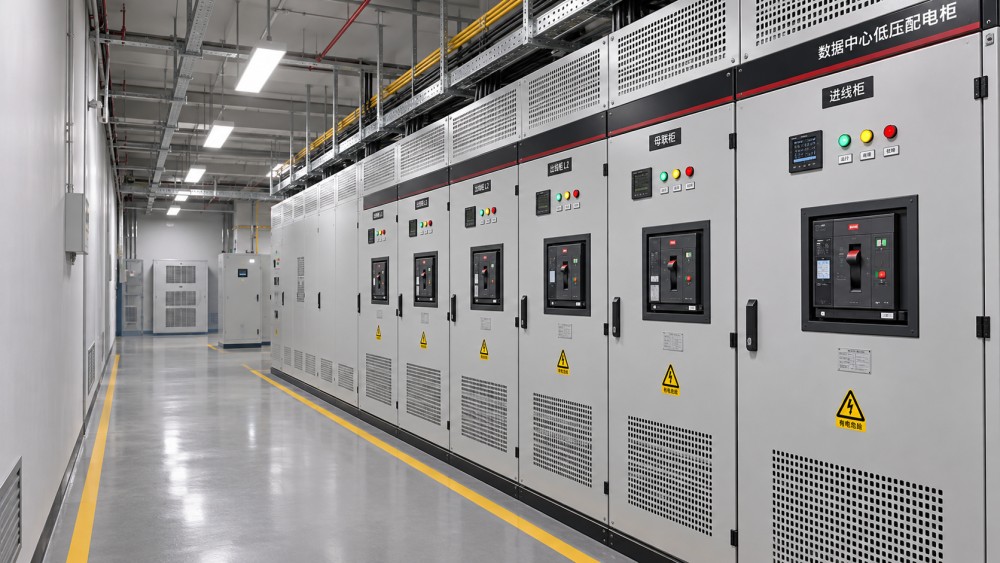
“Switchgear” can describe equipment at several points in a data center power system. A medium-voltage lineup at the utility interface, a low-voltage main distribution assembly, and an industrial control panel are not automatically evaluated under the same product standard. Voltage alone is not enough: construction, intended application, interrupting devices, and the scope of the relevant standard also matter.
For low-voltage assemblies, IEC 61439-1 sets out general rules, while IEC 61439-2 addresses power switchgear and controlgear assemblies within its scope. In the United States, UL 1558 addresses low-voltage power circuit breaker switchgear, whereas UL 891 addresses switchboards. A specification should not treat those two UL categories as synonyms: the equipment construction and applicable requirements differ. The appropriate category must be established from the actual design and intended installation.
Medium-voltage equipment requires a separate review. The IEC 62271 series covers high-voltage switchgear and controlgear, with individual parts addressing specific equipment types. In North American projects, relevant IEEE/ANSI standards and applicable certification or local requirements may also be involved. Do not apply a low-voltage assembly checklist to a medium-voltage lineup simply because both are called switchgear.
IEC verification: follow the assembly, not just the parts
Under IEC 61439, responsibility for design verification and routine verification must be clear. The original manufacturer establishes the verified design; the assembly manufacturer is responsible for the completed assembly and its routine verification. These roles can belong to the same organization, but a quality review should not assume that they do.
Design verification can use testing, comparison with a tested reference design, or assessment where the standard permits. Ask which method was used for each relevant characteristic and whether the supplied configuration remains within its documented limits. A test on one busbar arrangement does not automatically validate a different arrangement, enclosure, or protective-device combination.
For a low-voltage lineup, the review normally includes temperature-rise limits, dielectric properties, short-circuit withstand strength, protective circuits, clearances and creepage distances, and enclosure protection. Routine verification addresses the individual completed assembly through the checks required by the applicable standard. Request the actual verification records or an agreed evidence package, rather than accepting a statement that the design is “type tested.”
Pay particular attention to modifications made after design verification. A change in breaker frame, busbar material, compartment arrangement, ventilation, or cable termination can affect the basis of verification. The assembly manufacturer should document whether the change is covered by the original design rules or requires additional evaluation.
UL listing: establish exactly what is certified
A UL mark on an incoming breaker is evidence about that breaker, not necessarily about the completed switchgear lineup. For the assembly, obtain the certification identifier and confirm the manufacturer, product category, model or construction covered, and any conditions associated with the listing. Where available, check the listing through the certification organization’s current directory rather than relying only on a copied certificate.
Examine the nameplate and drawings against the certified configuration. A field-added section, substitute protective device, revised control circuit, or nonstandard interconnection may fall outside the original certification scope. This does not automatically make the equipment unsafe or unacceptable, but it does require a documented disposition. The manufacturer, certification body, and authority having jurisdiction may need to determine whether additional evaluation or a field evaluation is appropriate.
UL standards and a UL listing are related but distinct concepts. A supplier may claim that a design meets a UL standard without providing evidence that the actual assembly is listed. Conversely, a listing is not a substitute for confirming that the installed equipment satisfies the project’s electrical ratings and local installation rules.
Compare ratings with the data center power system
Standards evidence becomes useful only when it is matched to the conditions at the installation point. Obtain a current single-line diagram, load schedule, short-circuit study inputs, utility and generator source characteristics, and the intended operating configurations. During design changes, these documents can become inconsistent; the review should identify which revision is authoritative.
Continuous current and temperature
Compare the assembly and busbar current ratings with the calculated load, including planned expansion and the applicable design assumptions. Confirm ratings for incomers, bus sections, outgoing circuits, neutral conductors, and connections. Ambient temperature, altitude, enclosure ventilation, and adjacent heat sources can affect the permissible rating or require derating under the manufacturer’s instructions. A nameplate current alone does not establish capacity under every site condition.
Fault duty and protective devices
The available short-circuit current at each lineup must be within the applicable equipment and device ratings. Check the assembly’s short-circuit withstand rating and duration where specified, as well as the interrupting ratings of installed protective devices. In IEC documentation, short-time withstand current and conditional short-circuit current describe different arrangements; a conditional rating depends on the specified protective device and conditions. Do not substitute one for the other.
Generator contribution, utility source changes, transformer impedance, and parallel operating modes can alter fault duty. Confirm that the study covers normal, maintenance, and credible alternate-source configurations. Where a series-rated or conditional combination is proposed, verify the exact upstream and downstream devices and the permitted application; a similar device from the same product family is not enough.
Coordination and continuity of service
A compliant assembly does not guarantee selective protection. Review time-current characteristics and manufacturer selectivity data for the actual settings and fault levels. The aim is to understand which protective device will operate and what load will be lost, not to assume that every downstream fault is isolated perfectly. Document any limitation that could affect a redundant power path, maintenance bypass, or planned expansion.
Separate product compliance from installation safety
Product standards assess equipment within their defined scope. The installation must also meet the electrical code and other requirements adopted at the site. In the United States, the adopted edition of the National Electrical Code and local amendments are relevant, together with the decisions of the authority having jurisdiction. Other markets may adopt IEC-based installation rules or national variations. Determine the applicable editions and approval route early; an IEC or UL designation does not settle that question on its own.
Review enclosure suitability against the actual room and operating conditions. IEC IP ratings describe degrees of protection against access, solid objects, and water under specified tests. NEMA enclosure types use a different classification system and may include additional environmental considerations. An IP rating should not be converted into a NEMA type by a simple numerical equivalence without checking the underlying requirements.
Arc-flash risk also needs its own treatment. Evidence that equipment has passed an internal arc test under a specified standard and configuration should be read with the test conditions, accessibility criteria, and any stated limitations. It is not a blanket guarantee of worker safety, nor does it replace an arc-flash assessment, safe work procedures, or appropriate protective measures. Keep operating instructions, door-position restrictions, and maintenance requirements with the equipment records.
Turn the specification into an acceptance record
A useful submittal package connects each project requirement to a specific piece of evidence and the final equipment configuration. Before release for manufacture, ask the supplier to resolve gaps that could otherwise surface during inspection or commissioning:
- Define the compliance basis. Record the equipment category, applicable standard editions, site requirements, required certification, and any project-specific tests.
- Match the drawings to the evidence. Cross-reference lineup sections, bus ratings, devices, enclosure, fault ratings, and operating conditions to the design verification or certification scope.
- Agree on inspection points. Identify factory witness tests, routine verification records, nameplate checks, and the procedure for handling substitutions or nonconformances.
- Preserve change control. Require an assessment of whether changes after approval affect ratings, verification, certification, protection settings, or installation instructions.
- Confirm site acceptance. Compare delivered equipment with approved drawings and records; document shipping damage, field modifications, installation checks, and commissioning results.
Commissioning should follow the manufacturer’s instructions and the approved project procedures. Typical activities can include visual inspection, verification of connections and protective-device settings, and functional checks of interlocks and controls. The scope and test methods depend on the equipment and site; an additional field test must not exceed manufacturer limits or compromise sensitive components.
Where documentation conflicts, hold acceptance of the affected item until the discrepancy is resolved. A revised drawing, clarification from the assembly manufacturer, additional verification, or a formal evaluation may be needed. Record the decision against the final as-built configuration so that future maintenance and expansion do not rely on evidence for an earlier design.
Questions about data center smoke detection standards? Contact RackLedger for further insights.
We respect your privacy. Your information is strictly confidential.
Recommended News
 How Automatic Reclosers Restore Power After Transient Line FaultsAutomatic Reclosers restore power after temporary line faults. Discover how reclosing sequences, protection settings, and lockout support grid reliability.Nov 04, 2026
 Why Transformer Cooling Fans Fail and How to Diagnose Common FaultsTransformer Cooling Fans not working as expected? Learn how to diagnose common faults, check airflow and controls, and restore reliable cooling safely.Nov 04, 2026
 What Is Transformer Oil? Insulation and Cooling Functions ExplainedTransformer oil supports electrical insulation and cooling. Discover how it works, how it is tested, and why its condition matters for power reliability.Nov 04, 2026
 Sodium-Ion UPS Batteries vs. Lithium-Ion: What Buyers Should CompareSodium-Ion UPS Batteries vs. lithium-ion: compare runtime, safety, compatibility and lifecycle costs to make a confident data center buying decision.Nov 04, 2026