Related Industries
Curation by industry experts
Hot Articles
Popular Tags
Where Should Coolant Temperature Sensors Be Placed in a Loop?
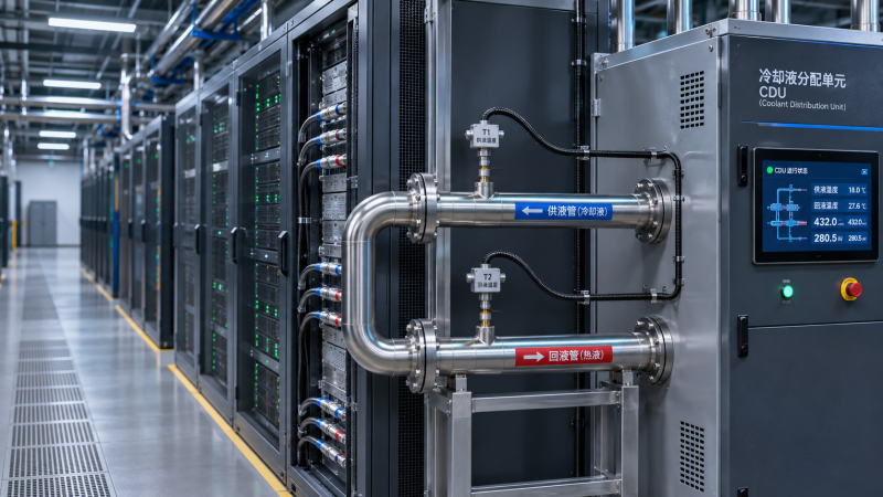
Where should coolant temperature sensors be placed in a liquid cooling loop? Start with the supply and return paths around the equipment you need to monitor: measure coolant entering the load and coolant leaving it. In a data center, that often means the secondary-side supply and return of a coolant distribution unit (CDU), with additional measurements closer to individual racks or equipment where temperatures may differ.
The right locations depend on the question each reading must answer. A CDU supply sensor can show whether the distribution system is delivering coolant at its target temperature, but it cannot guarantee that every server receives coolant within its specified range. Likewise, a return sensor helps show heat pickup, but it does not reveal every hot component inside a rack.
Start by defining the loop and the direction of flow
Before choosing sensor locations, identify the boundaries of the system. A typical direct-to-chip installation may have a facility water loop connected to one side of a CDU heat exchanger and a separate technology cooling loop connected to the other. The secondary loop carries coolant between the CDU and the IT equipment.
Each side has its own supply and return. A temperature labeled simply “CDU inlet” can be ambiguous: it may refer to facility water entering the CDU or warmed coolant returning from the IT load. Use labels that identify the fluid circuit, equipment boundary and direction of flow, such as “secondary supply to racks” or “facility water return from CDU.”
Also mark flow direction on the piping diagram. A sensor can be physically close to a CDU while measuring a very different condition depending on whether it is upstream or downstream of a mixing point, bypass or heat exchanger.
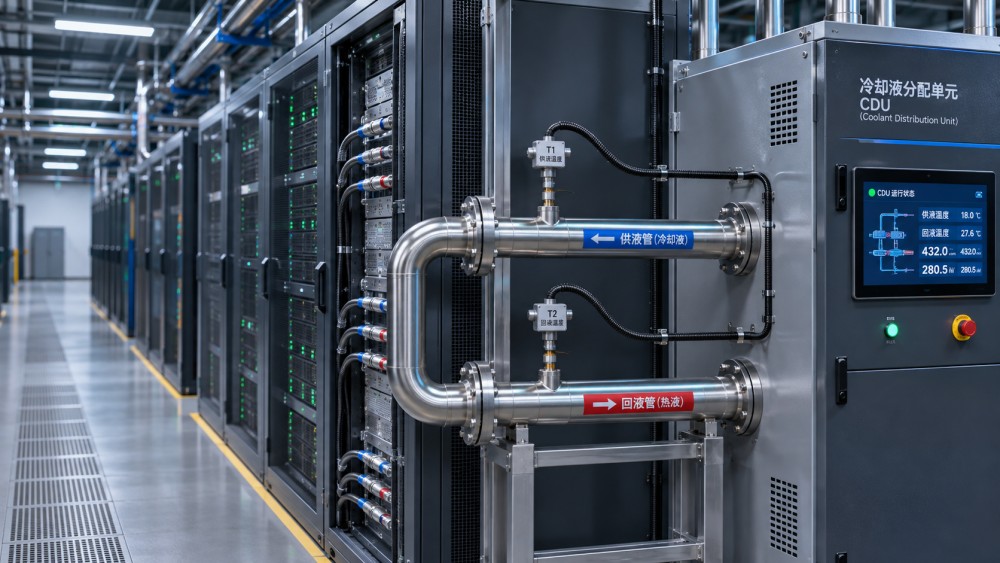
Which temperature measurements should a loop have?
For a CDU serving one or more racks, the most useful starting points are the secondary supply and return. Facility-side measurements add context when the CDU’s heat rejection or upstream water conditions are under review.
Not every installation needs a separate sensor at every point. Existing equipment may already provide some measurements through its controls or management interface. What matters is knowing exactly where those sensors are located, whether their data is available to operators, and whether they support the intended control or alarm function.
Why measure both supply and return?
The supply temperature shows the condition being delivered to the load. The return temperature shows the condition after the coolant has absorbed heat. The difference between them is commonly called the temperature rise, or delta T.
A change in delta T can be a useful diagnostic signal, but it is not a fault diagnosis by itself. At a similar heat load, lower coolant flow can produce a larger temperature rise across the equipment. A change in workload can also alter the temperature rise, even when flow is unchanged. To understand what is happening, compare temperature with flow measurements, equipment power and operating state where those data are available.
For a single-phase liquid, heat transfer can be estimated from flow, fluid properties and the supply-to-return temperature difference. The temperatures and flow must describe the same circuit and measurement boundary. Using a facility-water flow rate with secondary-coolant temperatures, for example, would not give a meaningful result.
Small temperature differences also make sensor accuracy important. Two sensors can each appear reasonable while their combined measurement error materially affects the calculated delta T. Matched sensors, appropriate calibration and consistent installation are especially useful when the temperature difference will be used for performance calculations or alarms.
When are rack-level sensors needed?
A CDU’s common supply reading is a useful control point, but it represents coolant at the CDU, not necessarily at each rack. Heat gain along distribution piping, different branch lengths, mixing and changing flow conditions can make individual inlet conditions differ.
Rack inlet measurements are particularly useful when a CDU serves several branches, when equipment has different coolant inlet limits, or when operators need to isolate a recurring temperature alarm. A rack outlet measurement adds visibility into that branch’s temperature rise. Together, the two readings make it easier to distinguish a warm supply from unusual behavior within a particular load.
However, a rack-level sensor still has a defined boundary. A sensor on the rack manifold may not read the exact temperature at every cold plate, especially if the internal distribution arrangement mixes flows or has multiple branches. Component telemetry remains necessary for identifying local problems such as poor thermal contact or uneven internal flow.
Where the design uses sampling rather than measurement at every rack, choose locations deliberately. A representative rack near the CDU may not reveal conditions at a more distant or differently loaded branch. The monitoring plan should reflect the piping layout and the consequences of missing an outlying condition.
Where should a sensor sit on the pipe?
Place the sensing element where it can measure representative, well-mixed fluid. Locations immediately beside a tee, bypass connection or mixing point can produce readings that reflect only part of the flow. Allow enough distance for mixing where the piping arrangement requires it, and follow the sensor and equipment manufacturers’ installation instructions.
Position matters around valves and pumps too. Ask whether the control system needs to know the temperature before or after a component. For example, a sensor downstream of a bypass mixing point measures the blended fluid; a sensor upstream measures only one of the contributing streams. Both may be useful, but they answer different questions.
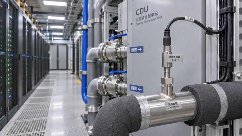
Immersion sensors, including probes installed in suitable thermowells, measure the fluid through a wetted or protected sensing arrangement. The probe must have appropriate insertion depth, pressure and temperature ratings, material compatibility and a connection suited to the system. A thermowell can simplify replacement without opening the coolant circuit, but its construction and fit can affect response time.
Surface-mounted sensors avoid introducing a probe into the fluid, but their readings are more sensitive to contact with the pipe, insulation and surrounding air. They can be useful for trending or a retrofit assessment, provided their limitations are understood. They should not automatically be treated as equivalent to a properly installed fluid-temperature sensor for a critical control or protection function.
Leave physical access for inspection, calibration and replacement. A sensor hidden behind permanently obstructed piping may be correctly positioned from a thermal perspective but difficult to maintain when it fails.
Should the control sensor be at the CDU or at the rack?
It depends on what the control system is designed to regulate. A CDU commonly uses a supply-side measurement to control the coolant temperature it delivers. That location provides a direct view of the CDU’s output and can support stable local control when the system is designed around it.
A rack inlet reading is closer to the equipment’s actual supply condition. It may be valuable for monitoring, alarming or, in a design engineered for it, as part of a broader control strategy. Distance, transport delay and changing branch conditions matter: a remote sensor can respond later than one at the CDU, affecting how a control loop behaves.
Do not move or substitute a control sensor solely because another location seems more representative. The sensor location, control settings, equipment limits and failure response need to work together. A remote rack reading can be added for visibility without necessarily replacing the CDU’s local control measurement.
How should alarms and redundancy be handled?
Set alarms against the condition each sensor actually measures. A CDU supply alarm can identify an output that has moved outside its operating target. An equipment inlet alarm can identify a condition at the load, which may be more directly relevant to the equipment’s coolant requirements. Alarm thresholds and delays should reflect the equipment specifications, control design and operating conditions.
Sensor failure also needs a defined response. A disconnected probe, implausible reading or stale communication value should not quietly appear as a normal temperature. The monitoring system should make the failure visible, and the controls should have a documented response appropriate to the equipment.
Redundant sensors can help when a measurement is critical, but two probes next to each other do not address every failure mode. They may share a controller, power supply, communication path or installation problem. Decide whether redundancy is intended to detect a failed sensor, preserve control during a failure, or provide an independent protective function; each objective may require a different arrangement.
What should be checked before commissioning?
Use the piping and instrumentation diagram to walk through the circuit from heat rejection to the IT load and back. For each measurement, record the tag, physical location, fluid circuit, flow direction and the system that receives the reading. Confirm that the display label matches the installed sensor rather than relying on a generic “supply” or “return” name.
During commissioning, check sensor calibration and signal mapping, then compare readings under conditions where their relationship is understood. Confirm that control valves and pumps respond as intended and that alarms reach the people responsible for acting on them. A simulated sensor fault can also reveal whether the control system and monitoring platform handle missing or invalid data as designed.
Finally, preserve a baseline with temperatures, flow, relevant equipment load and operating mode recorded together. A return temperature on its own says little about whether a loop is performing normally; a traceable set of measurements makes later changes much easier to interpret.
Can one temperature sensor be enough?
A single sensor can answer a narrow question, such as whether coolant leaving a small cooler is within a chosen range. It cannot show both the temperature delivered to a load and the temperature returning from it. For a shared data center loop, relying on one reading also leaves little visibility into branch differences or sensor failure.
Does a higher return temperature always mean there is a cooling problem?
No. Return temperature can rise because the IT load is doing more work, because flow has changed, or because supply temperature has increased. Compare it with the corresponding supply temperature, flow and equipment operating conditions before treating it as evidence of a fault.
Can existing server telemetry replace loop sensors?
Server telemetry can provide valuable component and equipment readings, but it may not expose coolant temperatures at the shared supply, return or CDU interfaces. Use it alongside loop measurements when operators need to understand both equipment health and the behavior of the cooling infrastructure.
Questions about data center smoke detection standards? Contact RackLedger for further insights.
We respect your privacy. Your information is strictly confidential.
Recommended News
 Data Center Variable Frequency Drives: Cutting Fan and Pump Energy UseData Center Variable Frequency Drives can cut fan and pump energy use. Explore retrofit opportunities, costs, risks, and practical steps to protect cooling reliability.Nov 04, 2026
 Why Is My Coolant Temperature Sensor Reading Too High?How do I troubleshoot a coolant temperature sensor that reads too high? Verify the reading, trace cooling and control faults, and protect data center equipment.Nov 04, 2026
 Where Should Coolant Temperature Sensors Be Placed in a Loop?Where should coolant temperature sensors be placed in a liquid cooling loop? Explore CDU supply, return and rack-level locations for reliable monitoring.Nov 04, 2026
 How Do I Size a Coolant Reservoir for a Liquid Cooling Retrofit?How do I size a coolant reservoir for a liquid cooling retrofit? Learn how to calculate usable capacity, check pressure and avoid costly sizing mistakes.Nov 04, 2026