Related Industries
Curation by industry experts
Hot Articles
Popular Tags
Data Center Variable Frequency Drives: Cutting Fan and Pump Energy Use
Data Center Variable Frequency Drives can reduce fan and pump energy use by adjusting motor speed to match cooling demand. The strongest candidates operate below design load for substantial periods.
For project managers, the decision depends on more than motor size. Controls integration, minimum cooling requirements, commissioning access, reliability, and lifecycle costs determine whether an upgrade delivers useful savings.
The practical starting point is to measure existing operating conditions, then compare a complete retrofit against maintaining the current system. Nameplate power alone is not a reliable savings estimate.
Which Data Center Fans and Pumps Are Good Candidates?
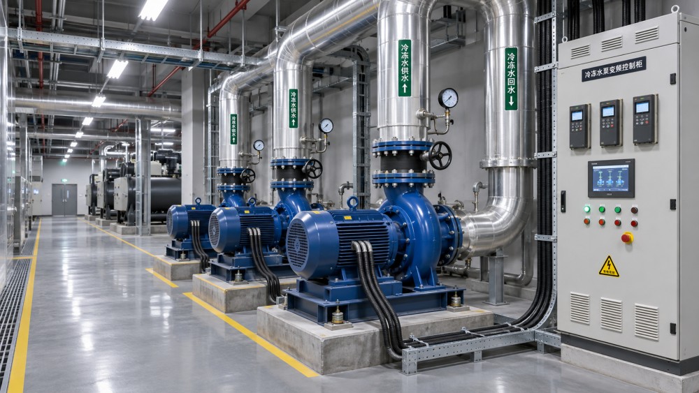
Look first for centrifugal fans and pumps that run continuously while dampers, valves, or bypasses restrict flow. These restrictions can indicate opportunities to match motor speed more closely to demand.
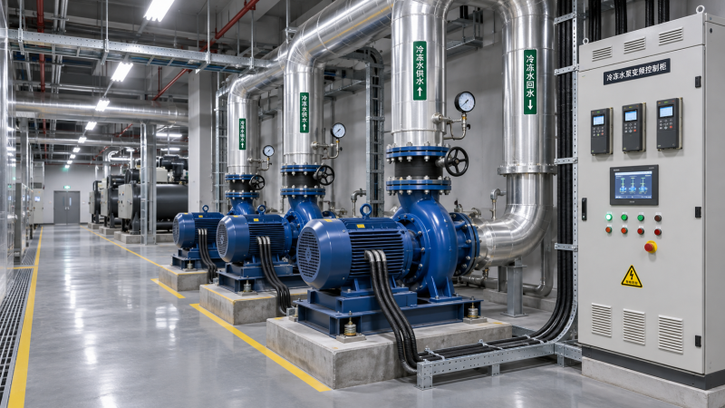
Common candidates include air handling unit fans, cooling tower fans, chilled-water pumps, and condenser-water pumps. Suitability depends on the system configuration and the manufacturer's operating limits.
A fan serving a consistently hot, fully occupied hall may have limited speed-reduction opportunities. By contrast, equipment sized for future capacity may spend considerable time below design load.
Check whether an existing motor already has a drive, an electronically commutated motor, or another effective speed-control method. Replacing functional controls may offer less value than addressing uncontrolled equipment.
For liquid-cooled facilities, assess secondary-loop pumps and coolant distribution units individually. A drive is only useful where the equipment design permits speed control without compromising flow, pressure, or thermal protection.
Do not assume every pump should slow whenever IT utilization falls. Some loops require minimum flow through heat exchangers, chillers, or cold plates, regardless of short-term workload changes.
How Much Energy Can Variable Speed Save?
For a centrifugal fan or pump operating under ideal affinity-law assumptions, flow varies approximately with speed and shaft power with the cube of speed. Real systems rarely follow this perfectly.
As an illustration, reducing speed from 100% to 80% gives an idealized shaft-power ratio of 0.8 cubed, or 51.2%. This is not a guaranteed reduction in electrical consumption.
Actual savings depend on the system curve, static pressure or lift, equipment efficiency, drive losses, minimum speed, and operating hours. Pumping systems with substantial static head can behave differently.
Consider a fan motor that measures an average electrical input of 40 kilowatts across 8,000 annual operating hours. Its baseline consumption is approximately 320,000 kilowatt-hours per year.
If validated analysis predicts an average input of 30 kilowatts after retrofit over the same hours, annual consumption would fall by approximately 80,000 kilowatt-hours before accounting for other system changes.
At an illustrative electricity rate of $0.12 per kilowatt-hour, that difference equals $9,600 annually. Actual financial savings depend on the applicable tariff, including demand charges and time-of-use rates.
Use a representative speed and load profile rather than applying one percentage to all hours. Include seasonal weather, redundancy operation, IT occupancy, and expected changes in cooling demand.
Account for the drive's own losses, changes in motor efficiency, and any additional cooling or control loads. Compare electrical input at consistent measurement boundaries before and after installation.
How Should Project Managers Build the Business Case?
Start with an equipment inventory that records motor ratings, measured power, operating schedules, existing controls, maintenance condition, and redundancy roles. Identify which assets can be isolated without interrupting service.
Estimate installed costs, not just drive prices. Include engineering, electrical protection, enclosures, cabling, filters, controls programming, installation, commissioning, training, documentation, and any required shutdown support.
Check motor compatibility and condition before finalizing the budget. Existing insulation, bearings, cooling arrangements, and cable lengths may require mitigation or make motor replacement a better option.
Calculate simple payback by dividing the incremental project cost by expected annual net savings. Use discounted cash flow when financing, equipment life, maintenance, and replacement timing materially affect the decision.
For example, a $60,000 installed project producing $9,600 in annual electricity savings has a simple payback of 6.25 years, before maintenance changes, incentives, financing, or equipment replacements.
Run sensitivity cases for electricity prices, operating hours, achieved speed reduction, and future IT load. A marginal project can become unattractive if the facility operates closer to design capacity.
Separately identify non-energy benefits, such as improved process control or reduced mechanical stress, only where evidence supports them. Avoid assigning monetary values that the project cannot reasonably substantiate.
If a utility incentive is available, confirm equipment eligibility, baseline measurement, approval timing, and verification requirements before ordering. An assumed rebate should not become committed funding prematurely.
What Electrical and Mechanical Risks Need Review?
A drive changes the electrical conditions experienced by the motor and upstream system. Engineering review should cover supply voltage, current, protection coordination, short-circuit ratings, grounding, and enclosure conditions.
Depending on the installation, harmonics may affect transformers, generators, or other sensitive equipment. Assess the combined load and applicable site requirements before selecting reactors, filters, or alternative drive configurations.
Motor cable length and switching characteristics can produce voltage stress. Ask the drive and motor suppliers to confirm whether output filtering, suitable cable, or an inverter-duty motor is needed.
Bearing currents and shaft voltages can also shorten motor life in some configurations. Evaluate grounding rings, insulated bearings, or other manufacturer-recommended measures against the actual motor and drive arrangement.
At low speeds, a motor's own cooling fan may provide less ventilation. Confirm that the motor can carry the expected load continuously across the proposed operating range.
Fans, pumps, piping, and supports can experience damaging vibration at particular speeds. Commissioning should identify resonance and configure skip frequencies where the equipment manufacturer and engineer consider them appropriate.
For pumps, verify minimum flow, pressure, suction conditions, and any chiller or heat exchanger requirements. For fans, verify airflow distribution and temperature limits at the most demanding served locations.
How Should Drives Integrate With Cooling Controls?
Define the control objective before selecting a communication protocol. Depending on the system, the drive may regulate duct static pressure, differential pressure, temperature, or another approved operating variable.
Place and validate sensors where they represent the controlling condition. A poorly located pressure sensor can cause excessive speed, insufficient flow, or unstable operation despite a properly installed drive.
Document setpoints, minimum and maximum speeds, acceleration rates, alarm thresholds, and equipment staging. Specify who owns each setting and how changes will be authorized after handover.
Coordinate the drive with the building management system and equipment controllers. Confirm network interfaces, command priorities, status points, alarm routing, time synchronization, and behavior during communication loss.
Set a deliberate failure response for each system. Depending on the cooling design, loss of a sensor or network command may require a defined speed, local control, standby equipment, or shutdown.
A bypass may be appropriate for some applications, but it is not automatically safe or necessary. Its design must account for motor starting current, protection, interlocks, and full-speed system behavior.
Test control interactions across operating modes, including normal demand, low load, equipment failure, and return from maintenance. Poorly coordinated loops can oscillate and erase expected savings.
Can the Retrofit Be Installed Without Affecting Availability?
Map each proposed outage to the facility's redundancy design and current maintenance status. Confirm that remaining equipment can support the actual load under the relevant environmental conditions.
Develop a method of procedure covering isolation, electrical safety, installation, testing, rollback, and communications. Obtain operations approval and schedule work within an agreed maintenance window.
Check whether temporary cooling or temporary pumping is required. Include rental equipment, connections, fuel or power, monitoring, and contingency time in both the schedule and business case.
Review equipment lead times early, including drives, protective devices, filters, compatible motors, and control components. Installation dates should reflect confirmed delivery and integration dependencies, not supplier estimates alone.
For phased rollouts, begin with a representative asset where measurement and isolation are practical. Use the results to refine design assumptions before committing to the remaining fleet.
Preserve as-built drawings, parameter backups, spare-parts lists, and vendor contacts. A retrofit is not operationally complete until the site team can troubleshoot and maintain the new configuration.
What Should Commissioning and Acceptance Prove?
Commissioning should demonstrate safe, stable cooling performance first and energy performance second. Define acceptance criteria before procurement so suppliers price the required tests and documentation.
Verify wiring, protection settings, rotation, sensor calibration, network points, and drive parameters. Test manual and automatic modes, alarms, interlocks, emergency responses, and recovery after a power interruption.
Demonstrate operation across the permitted speed range and check for vibration, noise, overheating, and unstable control. Confirm that minimum flow and critical temperatures remain within approved limits.
Test standby equipment and failure scenarios relevant to the design, including a failed drive, failed sensor, and lost communications. Record actual responses against the agreed sequence of operations.
Measure electrical power with appropriately specified instruments and record relevant operating conditions. Compare results with the baseline using consistent boundaries and adjustments for weather, IT load, and operating hours.
A short acceptance test can confirm function but may not establish annual savings. Plan follow-up monitoring across representative seasons, and assign responsibility for investigating deviations from the forecast.
Making the Investment Decision
Data Center Variable Frequency Drives are most compelling where centrifugal equipment runs for long periods below design demand and the cooling system can safely operate across a wider speed range.
Approve the project when measured opportunity, full installation costs, operational protections, and a credible verification plan support the investment. Where evidence is weak, gather operating data before committing capital.
For project managers, success means more than installing drives: the facility must maintain required cooling performance, the operations team must understand the controls, and measured savings must justify the disruption.
Questions about data center smoke detection standards? Contact RackLedger for further insights.
We respect your privacy. Your information is strictly confidential.
Recommended News
 Data Center Variable Frequency Drives: Cutting Fan and Pump Energy UseData Center Variable Frequency Drives can cut fan and pump energy use. Explore retrofit opportunities, costs, risks, and practical steps to protect cooling reliability.Nov 04, 2026
 Why Is My Coolant Temperature Sensor Reading Too High?How do I troubleshoot a coolant temperature sensor that reads too high? Verify the reading, trace cooling and control faults, and protect data center equipment.Nov 04, 2026
 Where Should Coolant Temperature Sensors Be Placed in a Loop?Where should coolant temperature sensors be placed in a liquid cooling loop? Explore CDU supply, return and rack-level locations for reliable monitoring.Nov 04, 2026
 How Do I Size a Coolant Reservoir for a Liquid Cooling Retrofit?How do I size a coolant reservoir for a liquid cooling retrofit? Learn how to calculate usable capacity, check pressure and avoid costly sizing mistakes.Nov 04, 2026