Related Industries
Curation by industry experts
Hot Articles
Popular Tags
Why Is My Coolant Temperature Sensor Reading Too High?
A coolant temperature sensor reading too high can signal a genuine cooling problem, a faulty sensor, or an issue with wiring and controls. For data center operators, distinguishing between these causes is essential before adjusting cooling capacity or replacing components. How do I troubleshoot a coolant temperature sensor that reads too high? Start by checking the reading against an independent measurement, then examine sensor placement, connections, flow conditions, and system alarms. This guide explains how to narrow down the cause while protecting equipment and maintaining reliable cooling operations.
Treat the alarm as real until you can prove otherwise
A high reading is not automatically a failed sensor. In a liquid-cooled data center, it may indicate that a coolant distribution unit (CDU) is receiving warmer facility water, that flow through a rack has fallen, or that heat load has changed faster than the cooling system can respond. It may also be entirely expected if the point being measured is a warm return line rather than a supply line.
Begin with the site’s alarm response procedure. Check whether equipment is approaching its documented operating limit, whether redundant cooling is available, and whether related alarms indicate low flow, pump failure or leakage. Escalate or reduce load according to the facility’s operating plan if equipment protection is at risk. Do not disable an alarm or override an interlock simply to keep a workload running.
Record the displayed temperature, alarm time, sensor identifier and current workload. Note recent maintenance, control changes or equipment additions. These details matter because an intermittent fault may disappear before a technician reaches the cabinet.
Confirm what the sensor is actually measuring
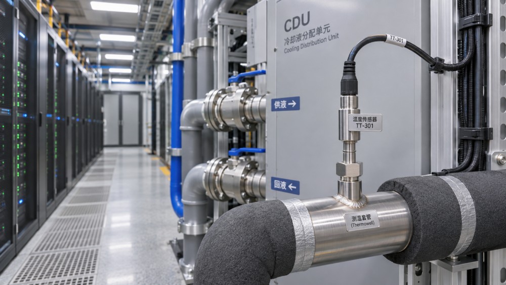
Before comparing temperatures, identify the sensor’s location on the current piping diagram. Is it on the facility-water side of the heat exchanger, the technology-cooling loop serving IT equipment, or an individual rack branch? Is it upstream or downstream of the load? Labels in a building management system can be misleading after a modification or point-mapping change.
A return temperature is expected to rise as coolant absorbs heat. Whether that rise is acceptable depends on the equipment limits, flow rate, coolant properties and operating conditions. Likewise, a warm supply temperature is not necessarily a fault if it remains within the approved range for the connected hardware. Compare the reading with the applicable equipment documentation and site setpoints, not with a generic temperature found online.
Use a calibrated reference instrument at the same measurement point where practical. A properly installed test port or approved measurement well provides a better comparison than a handheld device aimed at an exposed pipe. If only a surface measurement is available, account for insulation, pipe material, contact quality and ambient conditions. An infrared thermometer can be misleading on shiny metal; follow the instrument manufacturer’s guidance.
Allow both instruments time to stabilize, and document their accuracy and measurement method. A small difference may fall within the combined uncertainty of the instruments. A substantial or changing difference is more useful evidence, particularly if the reference measurement remains stable while the displayed value jumps.
Read the pattern, not just the temperature
Trend data often narrows the investigation faster than a component swap. Compare the suspect point with nearby temperatures, flow, pump status, valve position and IT load over the same period. Ensure the timestamps and sampling intervals match before drawing conclusions.
- A sudden step change in one reading: Look for a sensor, wiring, controller-input or configuration issue, especially if independent measurements and related points remain steady.
- A gradual rise across several points: Investigate a shared cooling constraint, such as warmer facility water, reduced heat-exchanger performance or an increase in load.
- A high return temperature on one branch: Check branch flow, valve position and load distribution. A local restriction can produce a different pattern from a system-wide supply problem.
- Brief spikes during workload transitions: Examine control response and sampling behavior as well as the physical system. A short-lived signal may be real, delayed or distorted by the monitoring chain.
These are diagnostic clues, not definitive fault codes. A shared controller or common wiring route can make multiple readings wrong at once, while a genuine flow issue can affect only one sensor’s location.
If the coolant is genuinely hot, follow the heat and the flow
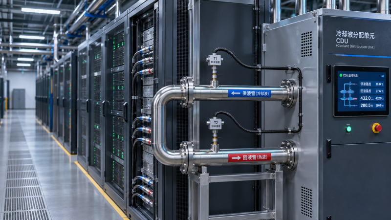
When the independent measurement supports the alarm, start with the operating boundary of the affected loop. Check the CDU’s supply and return temperatures, available flow and differential pressure, then compare them with the unit’s approved operating conditions. Confirm that pumps are running as intended and that the actual valve positions agree with the control commands.
A pump status indication alone does not prove adequate flow. A restriction, partially closed valve, air trapped in the loop or a problem with a flow-control device may reduce circulation even when the pump is energized. Use installed measurements and authorized diagnostic procedures; opening a pressurized loop or disturbing a strainer can create a leak or interrupt service.
Next, examine the heat-rejection path. If facility-side inlet water is warmer than expected, the CDU may have less ability to remove heat even though its own controls are functioning. If facility conditions are within specification but the temperature difference across the heat exchanger has changed under comparable load and flow, investigate fouling or another performance issue with the equipment supplier. A single temperature difference is not enough to diagnose a heat exchanger without the associated flow and operating context.
For high-density AI racks, check whether the load profile has changed since the cooling system was commissioned. A design that handled an earlier configuration may behave differently with another mix of accelerators, a new workload or a different distribution of heat across branches. Compare actual demand with the documented capacity of the entire path, including facility water, CDU, rack connections and controls—not just the rack’s nameplate rating.
If the reading is wrong, trace the measurement chain
A temperature point is more than a probe. The measurement passes through the sensor element, wiring, input module, controller configuration and often a supervisory system before it appears on a dashboard. A problem at any stage can make a normal coolant temperature look high.
Check installation and connections
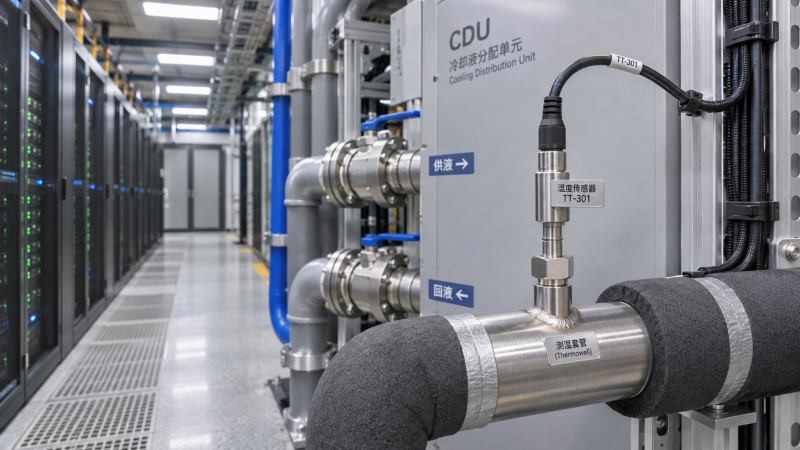
Inspect accessible connectors and cable routes for moisture, corrosion, loose terminations or physical damage, using the site’s electrical safety procedures. A poorly seated probe, an unsuitable thermowell installation or inadequate thermal contact can also make a sensor slow or unrepresentative. Compare the installation with the manufacturer’s instructions; do not remove a probe from a live or pressurized system unless the design and procedure explicitly permit it.
Electrical faults do not always produce the same apparent temperature. Whether an open circuit, short circuit or added resistance reads high, low or as a fault depends on the sensor type and controller configuration. Use the device documentation rather than assuming that one symptom identifies one failure.
Verify the controller configuration
Confirm that the input is configured for the installed sensor type and that any transmitter range, scaling and engineering units match the equipment documentation. Check for an incorrect offset, a Celsius-to-Fahrenheit conversion problem, a changed point mapping or a controller reading that differs from the supervisory display.
For example, if the local controller agrees with a reference instrument but the building management system does not, investigate communications and display configuration before replacing the probe. If both displays agree with each other but not with the reference, the issue may be upstream in the measurement chain—or the reference comparison may be flawed.
A qualified technician can test the input or sensor against the manufacturer’s published characteristics using suitable equipment and an approved isolation procedure. Simulating a sensor signal may also affect automatic control or trigger protective actions, so coordinate the work with operations. Record the original configuration before changing anything.
Replace components only after the evidence points there
Sensor replacement is reasonable when a verified comparison and manufacturer-approved tests show that the device is outside its specified tolerance, or when inspection confirms damage. But a new sensor will not correct an incorrect input type, a damaged cable or a hot coolant loop.
Before ordering, confirm the sensing element, temperature range, process connection, insertion length and compatibility with the existing controller. For a wetted component, also verify material compatibility with the coolant and the conditions of the loop. Establish whether replacement requires isolation, draining, leak testing or a maintenance window, and check the availability of the part and associated seals.
After repair, compare the reading with the reference again and observe the system through representative operating conditions. Verify the alarm path and control response under the site’s approved test procedure. Close the work record with the measured values, instrument used, configuration changes and any remaining uncertainty; that history will be more useful than a note saying only “sensor replaced.”
Use the incident to improve the next decision
Repeated high-temperature alarms deserve a broader review even when each event has an immediate fix. Check whether point names match the as-built drawings, whether trend retention is long enough to capture workload changes, and whether technicians can access reference measurement locations without disrupting service. During new deployments, include sensor verification, alarm testing and operating-boundary checks in commissioning and acceptance plans.
This is the kind of connection between equipment specifications and operating conditions that RackLedger’s planned data center and AI infrastructure coverage will examine. For the immediate troubleshooting decision, keep the evidence tied to the specific loop: confirm the measurement point, establish whether the temperature is real, and only then decide whether the next intervention belongs to cooling operations, controls or component maintenance.
Questions about data center smoke detection standards? Contact RackLedger for further insights.
We respect your privacy. Your information is strictly confidential.
Recommended News
 Data Center Variable Frequency Drives: Cutting Fan and Pump Energy UseData Center Variable Frequency Drives can cut fan and pump energy use. Explore retrofit opportunities, costs, risks, and practical steps to protect cooling reliability.Nov 04, 2026
 Why Is My Coolant Temperature Sensor Reading Too High?How do I troubleshoot a coolant temperature sensor that reads too high? Verify the reading, trace cooling and control faults, and protect data center equipment.Nov 04, 2026
 Where Should Coolant Temperature Sensors Be Placed in a Loop?Where should coolant temperature sensors be placed in a liquid cooling loop? Explore CDU supply, return and rack-level locations for reliable monitoring.Nov 04, 2026
 How Do I Size a Coolant Reservoir for a Liquid Cooling Retrofit?How do I size a coolant reservoir for a liquid cooling retrofit? Learn how to calculate usable capacity, check pressure and avoid costly sizing mistakes.Nov 04, 2026