Related Industries
Curation by industry experts
Hot Articles
Popular Tags
How Battery Management Systems Balance Cells and Prevent Overcharging
Battery management systems balance cells by measuring differences within a battery string and either removing charge from higher-voltage cells or transferring energy between cells. They help prevent overcharging through a separate set of controls: monitoring cell voltage and temperature, requesting changes to charging, and triggering protective action when limits are exceeded.
Those functions are related, but they are not interchangeable. A balancing circuit may correct gradual differences between cells while being far too slow to stop a charger that continues operating after a cell reaches its maximum voltage. For a data center battery system, the quality of protection depends on the entire response chain: sensing, control logic, communication, the charger or UPS, and the device that ultimately interrupts charging.
Why individual cells need attention
A battery string contains cells connected in series to reach the required voltage. The same current flows through each series-connected cell, but the cells do not necessarily have identical capacity, internal resistance, temperature, or self-discharge characteristics. Manufacturing variation and aging can make those differences more pronounced over time.
During charging, a lower-capacity or more highly charged cell can reach its upper voltage limit before the rest of the string. Pack voltage alone may still look acceptable because it is the sum of all cell voltages. A charger controlled only by that total can therefore continue delivering current while one cell is approaching an unsafe condition.
The corresponding issue occurs during discharge: the weakest cell can reach its lower voltage limit while other cells retain usable energy. In both directions, the first cell to reach its limit can constrain the usable capacity of the string.
Cell voltage is useful, but it is not a complete description of state of charge. The relationship depends on chemistry, temperature, current, and recent operating history. Some chemistries also have relatively flat voltage curves over part of their operating range, making small state-of-charge differences difficult to infer from voltage alone. A BMS may combine voltage measurements with current integration, temperature readings, and a model of cell behavior; the resulting estimate remains subject to measurement and model error.
How balancing changes the charging picture
Balancing aims to reduce differences among cells so that the string can use more of its available capacity without an individual cell reaching a voltage limit prematurely. The two main approaches differ in what happens to the energy removed from a higher-charge cell.
Passive balancing
In passive balancing, the BMS switches a small load, commonly a resistor, across selected cells. The resistor bypasses some charging current around a higher-voltage cell and dissipates energy as heat. This gives lower-voltage cells more opportunity to catch up as charging continues, within the limits of the charging strategy.
The approach is comparatively straightforward, but its balancing current and duty cycle determine how quickly it can correct an imbalance. If the mismatch is large, a low-current circuit can require a long balancing window. Heat dissipation, enclosure temperature, and the conditions under which balancing is enabled also affect how much correction is possible.
Active balancing
Active balancing uses a power-transfer circuit to move energy between cells, groups of cells, or another point in the battery system, depending on the design. It can recover some energy that passive balancing would dissipate as heat, although the transfer process has losses of its own.
Active designs may offer higher balancing currents or operate over a broader range of charge states, but neither outcome follows automatically from the label. The circuit topology, control strategy, thermal limits, and available operating time all matter. Added components and control complexity also create additional integration and diagnostic considerations.
For either method, a useful specification states the balancing current, when balancing begins and stops, which cells can be balanced simultaneously, and whether charging must be present. A headline current without its operating conditions says little about how quickly a particular string can recover from imbalance.
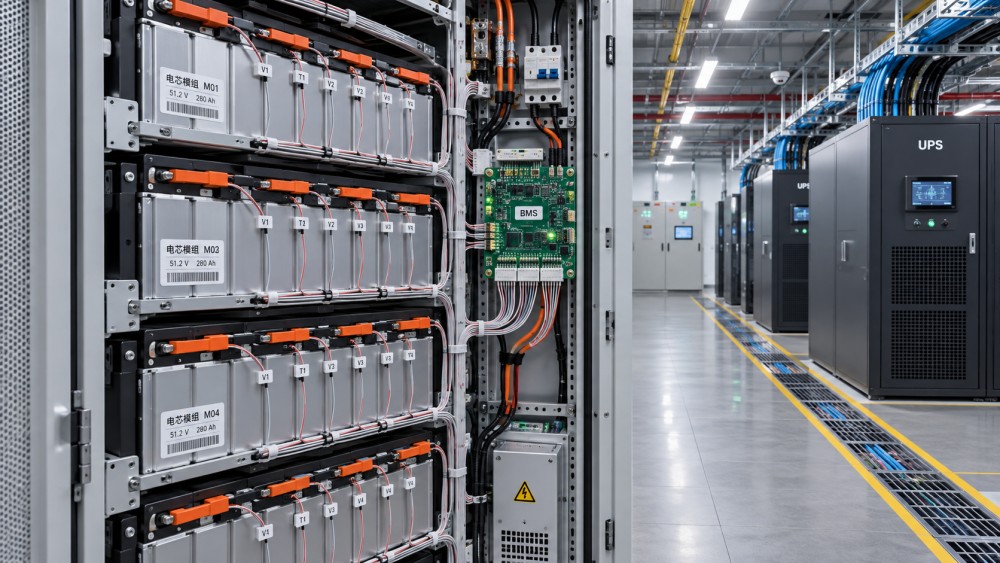
What happens as a cell approaches its charge limit
Overcharge protection generally begins with cell-voltage measurement. The BMS compares readings with thresholds defined for the cells and operating conditions. Depending on the system architecture, it may first report an alarm or ask the charger to reduce current, then request charging to stop, and finally initiate an independent protective action if the condition persists.
Temperature and current measurements contribute to that decision. Permitted charging current and voltage can depend on cell temperature, and a system may need to inhibit charging outside the cell manufacturer’s approved temperature range. Temperature sensors, however, measure only their installed locations; their number and placement affect whether they can identify a localized problem.
Different actions serve different purposes:
- Charge regulation keeps normal charging within specified voltage, current, and temperature limits.
- Balancing reduces cell-to-cell differences within the circuit’s available current and operating window.
- Protective shutdown responds when limits or other safety conditions are exceeded, using the available control and interruption devices.
A BMS may communicate a charge-current limit to a charger, issue a stop command, control a contactor, or use a combination of these measures. Exact responsibilities vary by design. An evaluator should identify which device makes each decision and whether it can act when communications fail, the charger ignores a request, or a switching device does not open as commanded.
Response time matters as much as the nominal threshold. The relevant interval includes measurement sampling and filtering, decision delay, communication delay where applicable, and the time taken for the charger or interruption device to stop current. At high charging current, a delay that appears small in a control specification can still matter. Threshold accuracy and sensor tolerances also affect the margin between the protective setting and the cell’s absolute limit.
Protection must account for the electrical behavior of the full system. Opening a battery contactor under load, for example, requires a device and circuit designed for the relevant DC voltage, current, and fault conditions. A command to open is not itself evidence that current has stopped; designs may use feedback or other diagnostics to detect a discrepancy.
Why balancing cannot be treated as a safety cutoff
Consider a cell that reaches its upper voltage limit while the charger is still supplying substantial current. A passive balancing resistor can divert only the current for which it is designed. If charging current exceeds that bypass capability, the cell may continue to gain charge despite balancing. Active balancing also has finite transfer capacity and cannot be assumed to absorb an arbitrary charging fault.
Balancing is likewise not a remedy for a failed or severely degraded cell. A recurring voltage deviation may reflect capacity loss, excessive resistance, a temperature difference, a connection issue, or a sensing problem. Repeatedly balancing the string may reduce the visible symptom without resolving its cause. Diagnostic procedures should distinguish a cell that needs time to equalize from one that requires inspection or replacement.
The inverse is also important: a protective trip does not demonstrate that the string is well balanced. A system can stop charging before any cell exceeds its limit yet deliver less usable backup capacity because one cell reaches that limit much earlier than the others.
Evaluating a BMS in a data center UPS
In a battery-backed UPS, charging behavior is shaped by more than the battery controller. The UPS charger, battery cabinet, monitoring network, protection devices, and site operating procedures all influence the result. A battery and UPS may each have suitable specifications in isolation while their combined behavior remains unclear.
Start with the intended operating profile. A standby battery may spend long periods at a prescribed maintenance state and only occasionally experience a deep discharge. Ask when the BMS is allowed to balance under that profile and whether the normal charging sequence provides enough time for it to do so. If balancing occurs only near the upper end of charge, changes to charging settings can affect both balancing opportunity and battery operation.
Then trace the response to a high-cell-voltage event from measurement through to the final action. Documentation and acceptance testing should establish:
- Which cell-voltage, temperature, and current limits apply, including their accuracy, delays, and any dependence on operating conditions.
- How the BMS communicates charge limits to the UPS or charger, and what each device does after a loss of communication.
- Which device stops charging, whether an independent protective path exists, and how the system detects a failed command or switching device.
- When balancing operates, its effective current and thermal limits, and how persistent imbalance is reported.
- What alarms, cell-level data, event records, and service access are available to operators diagnosing an abnormal string.
Testing should be agreed with the equipment suppliers and performed within their approved procedures. It may include verification of alarm handling, communication loss, charger response to permitted control commands, and protective-device feedback. Simulated signals or approved test modes may be appropriate where deliberately overcharging a cell would be unsafe. A simulated result should be identified as such: it may confirm the control path without proving every aspect of real cell behavior.
For a UPS installation, protection actions also have availability consequences. Disconnecting a battery can remove backup support for the affected string or system, depending on the architecture. Operators need to understand how the UPS reports that loss of support, whether redundancy remains, and what inspection and reset conditions apply. Automatic reconnection should be evaluated against the cause of the trip and the equipment manufacturer’s instructions.
The most useful evidence is therefore a coordinated set of limits, interfaces, and test results for the installed configuration. A BMS specification can describe what the controller is capable of; the integrated system must show how those capabilities are used when a cell approaches its limit and when a normal control action fails.
Questions about data center smoke detection standards? Contact RackLedger for further insights.
We respect your privacy. Your information is strictly confidential.
Recommended News
 How Automatic Reclosers Restore Power After Transient Line FaultsAutomatic Reclosers restore power after temporary line faults. Discover how reclosing sequences, protection settings, and lockout support grid reliability.Nov 04, 2026
 Why Transformer Cooling Fans Fail and How to Diagnose Common FaultsTransformer Cooling Fans not working as expected? Learn how to diagnose common faults, check airflow and controls, and restore reliable cooling safely.Nov 04, 2026
 What Is Transformer Oil? Insulation and Cooling Functions ExplainedTransformer oil supports electrical insulation and cooling. Discover how it works, how it is tested, and why its condition matters for power reliability.Nov 04, 2026
 Sodium-Ion UPS Batteries vs. Lithium-Ion: What Buyers Should CompareSodium-Ion UPS Batteries vs. lithium-ion: compare runtime, safety, compatibility and lifecycle costs to make a confident data center buying decision.Nov 04, 2026