Related Industries
Curation by industry experts
Hot Articles
Popular Tags
Thermal Interface Materials: Paste vs. Pads for Server Cooling
Thermal Interface Materials help transfer heat from server processors to heatsinks or liquid-cooling cold plates. Choosing between paste and pads, however, involves more than comparing advertised thermal conductivity. Contact pressure, surface gaps, operating temperatures, application consistency and maintenance all influence the result. The right choice is the one that works within the hardware’s mechanical design and remains dependable through its expected service life.
For a technical evaluator, the first question is not “Which material has the highest conductivity?” It is “What interface was this assembly designed to create?” A processor under a tightly controlled cold-plate mount presents a different problem from a row of power components with varying heights. One material is unlikely to be the best answer for both.
Start with the gap, not the datasheet headline
Even surfaces that look flat contain microscopic irregularities. Without an interface material, trapped air obstructs heat flow between the processor package and the cooling surface. Paste fills those irregularities and can form a thin bond line when the mounting system provides suitable pressure. A pad is a preformed sheet that compresses between surfaces; depending on its formulation and thickness, it may also accommodate a larger or less uniform gap.
That distinction matters because thermal resistance depends on more than the conductivity printed on a product sheet. Bond-line thickness, contact area and the resistance at both material-to-surface boundaries matter too. A simplified way to think about the material layer is thickness divided by conductivity and contact area, with contact resistances added. Real assemblies are less tidy: pressure is not always uniform, surfaces can bow, and the installed thickness may differ from the nominal value.
As a result, a high-conductivity pad is not automatically a lower-resistance interface than a paste. Equally, a thin layer of paste is not useful if it cannot reliably bridge the actual gap. Ask suppliers for resistance or impedance data at relevant thickness and pressure, including the test method. If those conditions differ from the server mount, use the figures as screening information rather than a predicted processor temperature.
Where paste tends to fit
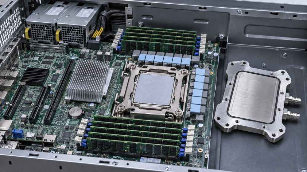
Thermal paste is often a practical candidate for a processor or accelerator package mated to a heatsink or cold plate with a controlled, relatively small gap. It conforms to surface irregularities, and the mount can squeeze it into a thin layer. That is valuable where heat is concentrated in a small area and interface resistance consumes a meaningful part of the temperature budget.
The trade-off is process control. Too little paste can leave uncovered regions; too much can spill beyond the intended area and complicate inspection or cleaning. Application pattern, quantity, surface preparation and mounting sequence should follow the hardware manufacturer’s instructions. “More paste for safety” is not a sound substitute for a verified application method.
Long-term behavior deserves the same attention as initial performance. Depending on the formulation and assembly, repeated temperature changes can move paste away from the contact area, a failure mechanism commonly called pump-out. Some compounds may also dry or separate over time. These are not reasons to reject all pastes; they are reasons to request aging evidence under conditions that resemble the intended workload and mounting design.
Electrical properties also vary. Do not assume that every paste is electrically insulating. If material can reach exposed components, confirm the supplier’s specifications and the equipment maker’s requirements. Liquid-metal products have distinct electrical and material-compatibility risks and should not be treated as interchangeable with conventional greases.
Where pads make the assembly easier—and where they do not
Pads can simplify installation where the design has a defined gap, particularly across components whose heights vary. A pre-cut part reduces dispensing variability and can make placement easier to inspect. This is often relevant around memory, voltage-regulation components and other devices cooled by a shared plate, rather than only at the main processor interface.
The apparent simplicity hides a mechanical constraint: the pad must compress enough to make contact without preventing the cold plate or heatsink from seating correctly elsewhere. An overly thick or stiff pad can increase force on a component or hold the assembly away from the processor. An undersized pad can leave a gap. Either problem can defeat an otherwise capable cooling design.
Evaluate the pad’s thickness tolerance, compressibility and compression force alongside its thermal properties. Verify the full stack-up, including component height tolerances, board deflection and mounting hardware. A soft pad may be easier to compress, but softness alone does not prove good thermal contact or long-term stability.
The word “pad” also covers different product types. Gap fillers, phase-change interface sheets and other preformed materials can have different installation and operating requirements. A phase-change material, for example, may need to reach its specified activation conditions before it conforms as intended. Compare the actual material and assembly instructions, not just the shape in which it is supplied.
What changes in a high-density or liquid-cooled server?
A cold plate does not eliminate the interface problem. It improves heat removal downstream of the package, but heat must still cross the material between the package and plate. In an accelerator server with limited junction-temperature headroom, an interface that performs poorly under the actual mounting pressure can constrain performance even when coolant flow and inlet temperature are within specification.
At the same time, a processor temperature rise is not proof of a TIM problem. Workload, device power, sensor location, coolant inlet temperature, flow, cold-plate condition and ambient conditions can all affect the reading. For air-cooled equipment, airflow distribution and heatsink fouling add further variables. Replacing the interface material before checking those conditions can turn a diagnosis into guesswork.
Training and inference workloads may also exercise equipment differently. A sustained high-load test is useful for establishing steady-state thermal behavior; repeated changes in load can expose a different set of mechanical and aging stresses. The relevant pattern depends on how the server will actually operate, including idle periods, power cycling and maintenance schedules.
For liquid-cooled assemblies, check material compatibility within the complete service environment. The TIM is normally at the external package-to-cold-plate interface, not intended to mix with coolant, but leaks, cleaning agents or maintenance procedures may create exposure. Follow the equipment supplier’s restrictions rather than assuming that compatibility with one surface or fluid covers the entire system.
Run the comparison in the actual mounting system
A useful evaluation begins with the server and cold-plate or heatsink manufacturer’s approved materials and service instructions. Changing the interface may affect mounting performance, support terms or warranty coverage. If an alternative is being considered, obtain the necessary approval and define who is responsible for validation before modifying production equipment.
Test candidates using the same hardware revision, mounting components, installation procedure and controlled operating conditions. Record device power and workload, coolant or inlet-air conditions, relevant temperatures and the point at which readings stabilize. Use comparable sensors and measurement locations. Temperature differences without those details are difficult to interpret, especially when processor power or cooling conditions are changing.
A single good installation is not enough to assess a fleet process. Include repeated assemblies and, where practical, different trained installers. Inspect coverage after a controlled teardown, recognizing that separation itself can alter the material pattern. For pads, check compression and any evidence that the plate did not seat as intended. For paste, look for uncovered areas, excessive spread and changes after representative operating cycles.
Define acceptance criteria before the test: allowable device temperature or thermal margin under a specified load, installation repeatability, mechanical limits and the condition after aging or cycling. The appropriate thresholds must come from the hardware limits and the project’s reliability requirements. A lower initial temperature is useful, but it should not override an unacceptable mounting force or an unstable result after cycling.
Serviceability can decide a close comparison
In a production data center, the material is only one part of the cost. A paste may require controlled dispensing, approved cleaning supplies, surface inspection and technician training whenever an assembly is opened. A pad may reduce application variability, but its exact thickness and cut shape must be available at the point of service. Some materials are intended for replacement after separation; do not assume a removed pad or previously compressed interface can be reused.
Ask how replacement parts are packaged, stored and identified, including shelf life and lot traceability where applicable. For a global fleet, confirm lead times and local availability of the approved material rather than planning around a nominally equivalent substitute. A service team should be able to identify the right material for a specific hardware revision without relying on appearance alone.
The operational risk becomes sharper when a cold plate must be removed during component replacement. The service procedure may involve more than the interface itself: isolation, draining or handling of liquid connections can also affect downtime. Those steps depend on the cooling architecture and supplier instructions, but they belong in the comparison because a small material saving can be outweighed by a difficult or error-prone repair.
Make the choice against the assembly’s real constraints
Choose paste when the approved design calls for a thin interface, the mounting system controls the gap, and the application and service process can be reproduced reliably. Consider a pad where the design needs a preformed gap-filling material and its compressed thickness and force are compatible with the whole assembly. Neither recommendation overrides the equipment manufacturer’s specified interface.
Before committing, ask for the mounting drawing, allowable pressure or force, gap tolerances, supplier test conditions and replacement procedure. Then validate the candidate in the server configuration and workload that matter. If the team cannot explain how the material seats, how it ages and how it will be replaced in the field, the conductivity number is not yet a basis for a decision.
Questions about data center smoke detection standards? Contact RackLedger for further insights.
We respect your privacy. Your information is strictly confidential.
Recommended News
 Choosing Server Rack Vibration Dampers for Sensitive IT EquipmentChoose Server Rack Vibration Dampers with confidence. Explore load, frequency, anchoring, and supplier criteria for sensitive IT equipment.Nov 04, 2026
 How rack power density affects prefabricated data center rack capacityDiscover how rack power density affects prefabricated data center rack capacity, and learn to assess power, cooling, redundancy, and layout limits.Nov 04, 2026
 Server Chassis Airflow: Why Hot Spots Form and How to Fix ThemServer Chassis hot spots can develop even in cool data centers. Discover how to trace airflow issues, fix common causes, and verify cooling performance.Nov 04, 2026
 Choosing Server Rack Shelves: Load Capacity, Depth and MountingServer Rack Shelves made simple: compare load capacity, usable depth and mounting options to choose a safe, compatible shelf with confidence.Nov 04, 2026