Related Industries
Curation by industry experts
Hot Articles
Popular Tags
What should prefabricated data center factory testing verify?
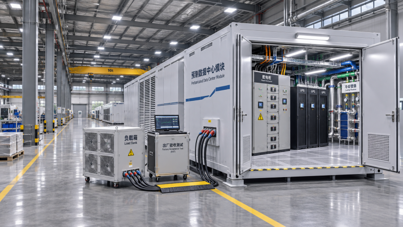
Before a prefabricated data center leaves the factory, quality control and safety teams need evidence that its integrated systems perform as specified—not just that individual components pass inspection. Prefabricated data center factory testing should verify electrical protection, power transfer, cooling performance, controls, alarms, and safety functions under agreed operating conditions. The factory acceptance test also needs to make clear what could not be reproduced until the module reaches its site.
That distinction matters when a unit arrives with a complete set of component certificates but an unresolved interface problem. A correctly functioning UPS, for example, does not by itself prove that the assembled power system will transfer as intended. Likewise, a cooling unit’s nameplate rating does not establish that the installed arrangement can remove the specified heat under the project’s actual water and ambient conditions.
Start with the acceptance boundary, not the test equipment
A factory acceptance test, or FAT, is an agreed inspection and demonstration of equipment before shipment. For a prefabricated data center, its scope may cover an entire module, several connected modules, or a subset of equipment assembled in a factory. The purchase agreement and test plan should define exactly which configuration is being accepted.
Before witnessing begins, quality personnel should reconcile the test setup with the approved design. That includes equipment models, ratings, firmware, protection settings, control sequences, redundancy arrangements and relevant drawing revisions. If temporary factory power, a simulated network or an external cooling source replaces a permanent site interface, the substitution belongs in the record.
The most useful FAT plan ties each requirement to a test method, operating condition, acceptance criterion and evidence record. It also identifies who can approve deviations and which failures prevent shipment. A statement such as “cooling operational” is difficult to defend; a defined load, inlet condition, measurement period and allowable operating range give the result meaning.
Electrical testing: prove the intended power path
Electrical inspection begins with the physical build. Teams should check equipment identification, cable routing, terminations, protective barriers, labeling, grounding and bonding against approved drawings and applicable requirements. Accessibility matters: a panel may be correctly assembled yet leave insufficient working space once adjacent equipment or shipping restraints are installed.
Appropriate electrical tests depend on the design, voltage and applicable rules. They can include protective-conductor continuity, insulation resistance and checks of phase sequence and polarity. Test voltages and procedures must be suitable for connected equipment; sensitive electronics may need isolation in accordance with manufacturer instructions. These activities should be performed by qualified personnel under an approved safety procedure.
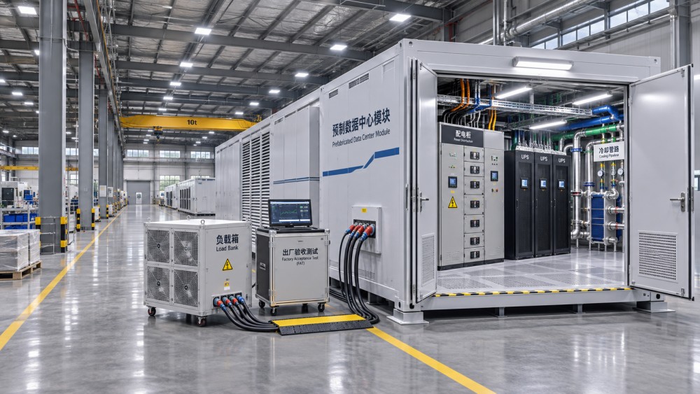
Functional testing should then follow the power path from the available factory supply through switchgear, UPS equipment and distribution to representative output points. Depending on the design, the witness plan may include:
- Verification of breaker status, interlocks, metering and protective-device settings against the approved coordination study or settings schedule.
- UPS operation on its normal source, transfer to stored energy, return to normal operation and bypass behavior, where the test setup permits.
- Automatic transfer between available sources, including the correct indication and sequence of switching devices.
- Responses to agreed fault or abnormal conditions, using safe simulation where applying a real fault would be unsafe or impractical.
A simulated generator signal can demonstrate part of a transfer sequence, but it does not prove that the site generator will start, accept load or operate with the installed fuel and exhaust systems. Record that boundary rather than treating a simulation as a complete end-to-end test.
Load-bank testing can provide evidence of electrical performance under a defined load profile. The report should identify the load applied, duration, voltage, frequency, measurement locations and any relevant power-quality observations. A resistive load bank is not necessarily representative of the changing power characteristics of AI servers; where workload behavior matters, the limitation should be explicit.
Cooling tests need a stated load and heat-rejection path
Cooling acceptance is especially sensitive to test conditions. A module designed for high-density computing may include air cooling, liquid cooling or both. In each case, the question is not simply whether pumps and fans start, but whether the assembled system controls heat under the conditions it was designed to handle.
For air-cooled arrangements, verify airflow paths, fan operation, temperature sensors and control response. Measure relevant supply and return conditions while applying an agreed heat load. Check that alarms and protective actions occur at approved setpoints, and examine whether obstructions, blanking arrangements or temporary test fixtures affect the result.
For direct-to-chip or other liquid-cooling interfaces, the factory plan should address the coolant distribution unit, piping, valves, instrumentation and connections included in the supplied scope. Depending on the design, checks may include:
- Pressure and leak testing to an approved procedure, with test medium, pressure, duration and acceptance criteria recorded.
- Verification of flow, differential pressure, supply and return temperatures, and control response at agreed operating points.
- Pump changeover, loss-of-flow indication and leak-detection response, including the location and handling of simulated leak signals.
- Identification of coolant and material compatibility requirements, filtration, cleanliness expectations and connection points for the site system.
Pressure testing itself creates a safety risk. The method, stored-energy hazards, exclusion zones and component limits need review before testing; pneumatic and hydrostatic methods are not interchangeable without engineering assessment.
Factory water temperature, available flow and heat-rejection capacity may differ from those at the destination. If a temporary chiller substitutes for the permanent facility water system, document its contribution and operating limits. A successful test at one inlet temperature and rack configuration should not be presented as proof of performance across every intended operating condition.
Controls, alarms and safety functions must work together
Integrated controls can hide small failures until several systems interact. A sensor might read correctly at its device while the building management system receives the wrong value, or an alarm might appear on a local display without reaching the agreed remote interface.
Test the complete signal path where possible: initiate the condition, verify the field input, observe the controller response and confirm the indication at the intended local or remote point. The point list should identify signal names, priorities, units, setpoints and expected actions. Where a customer network or site management platform is unavailable, use an agreed simulator and identify what remains for site verification.
Functional sequences deserve particular attention during abnormal operation. Examples include loss of a cooling pump, a UPS alarm, a high-temperature condition or failure of a communication link. The FAT should establish whether the system generates the right alarm, starts any intended standby equipment and returns to the appropriate state after the condition clears. It should also identify actions requiring operator intervention.
Safety teams should examine emergency stop arrangements, access controls, warning labels, guarded moving parts and the safe isolation points needed for maintenance. If fire detection, suppression or gas detection is supplied, verify its interfaces and approved cause-and-effect logic within the factory scope. A simulated release signal is not the same as discharging a suppression system, and any live discharge or impairment requires a separately approved procedure and safety controls.
Which standards apply to a factory acceptance test?
There is no single universal FAT checklist that automatically covers every prefabricated data center. Applicable requirements depend on the destination, equipment, contract and authority having jurisdiction. The project team should establish the governing editions before testing rather than selecting standards after results are available.
Depending on scope and jurisdiction, relevant references may include the IEC 61439 series for low-voltage switchgear and controlgear assemblies, IEC 62040 series for UPS equipment, and ISO 8528 series for generator sets. Data center design or operational frameworks, such as the EN 50600 or ISO/IEC 22237 series, may also inform project requirements. In North America, applicable electrical and fire codes and equipment listing requirements may differ. A reference to a standard does not, by itself, establish compliance or replace the manufacturer’s required tests.
Quality teams should separate three kinds of evidence: component certification or routine test records, assembly-level inspection and functional testing, and integrated demonstrations specified in the FAT. Each answers a different question. If a requirement is verified by review of a supplier certificate rather than witnessed testing, the test record should say so.
Turn test results into a controlled shipment decision
For each test, retain the procedure revision, date, equipment identification, instrument identification and calibration status, actual setup, observed readings, acceptance limits and witness signatures or electronic approvals. Screenshots and trend logs can be valuable, provided they are associated with the correct test and operating conditions.
Nonconformities need more than a note that they were “resolved.” Record the defect, its potential safety or performance effect, the responsible party, corrective action and any retest. An open-item register should distinguish shipment-blocking issues from items accepted for completion later, with written risk acceptance and an owner for each deferred action.
Shipping readiness is also a quality and safety question. Check preservation, drainage or protection of cooling circuits where required, transport restraints, loose components, environmental limits and handling instructions. Document the module’s condition before dispatch so that damage or changes can be identified on arrival.
What must still be verified on site?
Factory acceptance reduces uncertainty; it does not replace site acceptance testing and commissioning. Transport, reconnection and the permanent environment introduce conditions that may not exist in the factory. Site work should recheck shipping damage, grounding and bonding, cable and pipe terminations, utility interfaces, network connections and safety systems affected by installation.
Integrated site tests may then exercise the actual utility supply, generator, heat-rejection plant, building controls and operational procedures as applicable. The commissioning plan should trace deferred FAT items to those tests and define the evidence required for closure. Full-load or failure demonstrations should only proceed under approved procedures that protect personnel and connected equipment.
The strongest handover is therefore not a single “pass” certificate. It is a traceable account of what was tested, under which conditions, what remains open and who will verify the interfaces that only exist at the destination. For quality control and safety teams, that record turns factory testing into a practical foundation for a safer installation and a more credible acceptance decision.
Questions about data center smoke detection standards? Contact RackLedger for further insights.
We respect your privacy. Your information is strictly confidential.
Recommended News
 How Do Liquid-Cooled Server Test Results Compare to My Workload?How do I compare liquid-cooled server test results with my actual workload? Match power, coolant conditions and performance to plan your deployment with confidence.Nov 04, 2026
 What should prefabricated data center factory testing verify?Prefabricated data center factory testing verifies power, cooling, controls and safety. Discover what to check before shipment and what must be tested on site.Nov 04, 2026