Related Industries
Curation by industry experts
Hot Articles
Popular Tags
Rack Servers Explained: How They Fit into Data Center Infrastructure
Rack servers are computers built to mount in standardized equipment cabinets, where they share space and facility infrastructure with networking, storage, and power distribution equipment. Each server has its own processors, memory, storage interfaces, and power supplies, but its usable performance also depends on the power, cooling, network connections, and maintenance space available around it.
A rack can hold many servers in a small footprint. That density simplifies some aspects of deployment while concentrating heat, electrical demand, cables, and service activity. A server that fits between the mounting rails is therefore only one part of a workable installation.
From individual server to data center rack
A rack server is a self-contained chassis designed to slide onto rails or mounting hardware inside a rack. Unlike a desktop computer, it is generally built for front-to-rear airflow, remote management, and operation alongside other equipment. Its front and rear panels provide access to components and connections, although the exact service layout varies by model.
Rack height is expressed in rack units, abbreviated as U. One rack unit equals 1.75 inches of vertical mounting space. A 1U server occupies one unit, while a 2U server occupies two. Height alone does not describe capacity: a taller chassis may accommodate more drives, larger heat sinks, additional expansion cards, or accelerators, but its actual capabilities depend on its design.
The rack itself is a cabinet or open frame with vertical mounting rails. A nominal 19-inch rack describes the mounting interface, not the full external width of the cabinet or the depth available for equipment. Servers also vary in depth. Rails, power cords, network connectors, and cable-management arms need room beyond the chassis, so a server that appears to fit on paper can still interfere with a rear door or cable route.
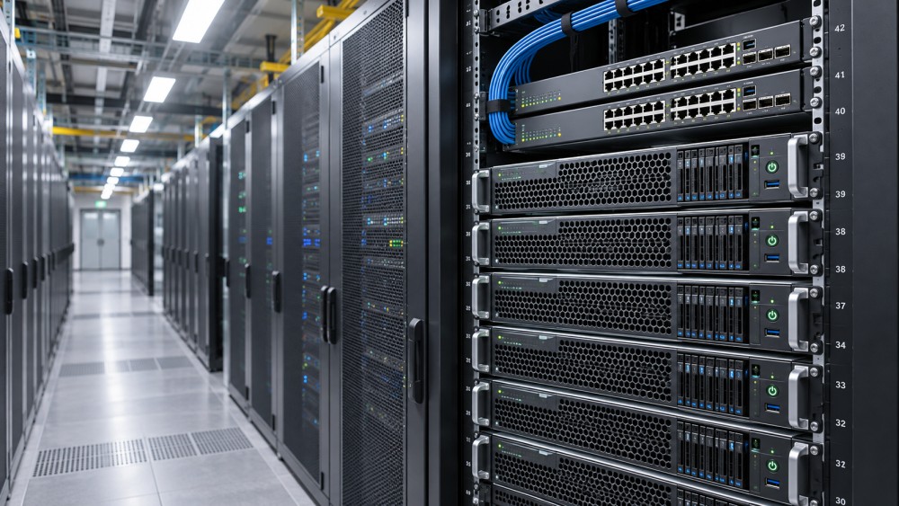
A populated rack might contain servers, network switches, and rack power distribution units, or PDUs. Some installations also include storage appliances or cooling-related equipment. Those devices consume vertical space and introduce their own power, airflow, and access requirements; the full rack layout must account for them before server capacity can be determined.
Where rack servers fit in the infrastructure
A rack server sits at the endpoint of several connected systems. Electrical power travels from the facility distribution system through rack-level equipment to the server power supplies. Network ports connect it to switches and onward to other servers, storage, and external networks. Cooling removes the heat generated by the components, while management connections allow administrators to monitor and control the machine remotely.
These paths meet at the rack, but their capacities are established across the wider facility. Adding servers may be physically straightforward while exceeding the available electrical allocation, cooling capability, or network port count. Conversely, a rack with unused power may be unable to accommodate more equipment because of airflow restrictions or insufficient service clearance.
Rack servers can also be compared with blade servers and tower servers. A blade server fits into a shared enclosure that supplies common functions such as power and networking; the enclosure itself must fit the facility. A tower server resembles a freestanding computer and may be suitable where rack infrastructure is limited. Rack servers offer a modular middle ground: individual chassis can be installed or replaced without requiring a shared blade enclosure, provided the rack and supporting services have capacity.
Power: distinguish nameplate, workload, and rack capacity
Server power supplies carry rated capacities, but those ratings do not automatically represent continuous consumption. Actual draw changes with processor utilization, accelerator activity, memory, drives, and configuration. Equally, an average measured during a light workload does not establish the maximum demand the electrical system must support.
For a deployment estimate, the useful distinction is between expected operating demand, possible peak demand, and the capacity reserved by the facility design. Server configuration and workload measurements provide a stronger basis than multiplying the largest power-supply rating by the number of machines. The resulting estimate still needs to be reconciled with the facility's electrical design and operating requirements.
At rack level, power also has to reach the equipment through compatible connectors, circuits, and PDUs. Available capacity is not necessarily interchangeable across every outlet: circuit and phase loading, redundancy arrangements, and individual PDU limits affect what can be connected. A rack with spare outlets can still lack usable electrical capacity.
What redundant power supplies do
Many servers have two power supplies so that one can continue supporting the system if the other fails. This arrangement only extends beyond the server when the supplies are connected to appropriately independent power paths. Two cords plugged into the same PDU do not protect against failure of that PDU or its upstream feed.
Each surviving path must also be able to carry the intended load after a failure. Under normal conditions, the two feeds may share demand; sizing each only for its normal share leaves a potential overload when one path is lost. The actual behavior depends on the server power-supply configuration and the facility's distribution design.
Cooling follows the heat, not just the rack count
Nearly all electrical power consumed by IT equipment ultimately becomes heat that must be removed. For air-cooled servers, fans draw cooler air through the chassis and discharge warmer air, typically toward the rear. Data centers organize racks and airflow paths to reduce mixing between supply and exhaust air.
Density matters because the same room can behave differently when heat is spread across many racks or concentrated in a few. A room-level cooling total does not prove that enough cool air reaches every server inlet. Obstructed perforated tiles, gaps that allow hot exhaust to recirculate, and mismatched equipment airflow directions can create local hot spots even when overall cooling equipment has spare capacity.
Empty rack openings are relevant too. Without blanking panels or another effective barrier, hot exhaust air can move through unused spaces toward the front of the rack. Similarly, cable bundles or equipment positioned in the airflow path can restrict ventilation. Server inlet temperatures provide more useful evidence of local conditions than a single room temperature reading.
Accelerator-heavy servers can place greater cooling demands on a rack than conventional configurations. Some use direct-to-chip liquid cooling, where a liquid loop carries heat away from selected components. Other components may still require air cooling. A liquid-cooled server therefore needs compatible facility connections, coolant management, monitoring, and service procedures in addition to any remaining airflow capacity. The presence of liquid cooling does not by itself establish how much heat is removed through each path.
Physical fit includes service access
A rack layout should account for more than the number of open U positions. Chassis depth, rail compatibility, rack door clearance, floor loading, and access to power and network ports all influence whether a configuration can be installed and maintained. Heavy servers or densely populated storage chassis also affect lifting arrangements and how weight is distributed within the rack.
Maintenance introduces space requirements outside the cabinet. A server on sliding rails may need to extend into the aisle for service; the required clearance depends on the chassis and rail design. Cable-management arms can allow a server to slide out with cables attached, but they occupy space and do not eliminate bend-radius or cable-length constraints.
Component access varies. Some drives and power supplies can be replaced from the front or rear while the chassis remains mounted. Other work requires the server to be extended, shut down, or removed. Closely packed racks should be assessed against the actual service procedures for the installed equipment, not just the advertised ability to mount it.
Networking and storage connections
Each server needs network connectivity appropriate to its workload. A simple configuration may use connections for application traffic and remote management; a larger system can require separate paths for storage, clustering, or accelerator communication. Port speed is only one part of the design. The number of ports, switch capacity, cable type, distance, and available transceivers must also align.
Physical organization affects reliability. Tight bends, unsupported cable weight, and cables routed across removable components can turn a straightforward replacement into a disruptive task. Labels at both ends and enough slack for the intended service movement make connections easier to trace without leaving excessive cable in the airflow path.
Storage may be installed inside each server or accessed over a network from separate equipment. Local drives reduce dependence on a storage network for those devices, while shared storage introduces network and storage-system dependencies. Neither arrangement determines application availability on its own; software design, redundancy, backup, and recovery procedures also matter.
Reading server specifications in context
Processor count, memory capacity, drive bays, and accelerator slots describe what a chassis can hold. They do not establish the performance of a particular application without its software, data flow, utilization, and configuration. A server with more accelerators, for example, may be constrained by available network bandwidth, memory, storage throughput, or power.
Similarly, a rack power figure needs a clear boundary. A rating for a server chassis is different from a rack PDU rating, an allocated rack power budget, or the actual power measured over time. When comparing figures, identify whether they describe a limit, an expected load, or an observed peak, and whether supporting equipment is included.
Environmental specifications require the same care. Equipment inlet temperature and humidity ranges describe conditions at the server, not necessarily the reading at a room thermostat. Operating within a published range also does not automatically guarantee a particular fan speed, energy use, or performance under every workload.
From installation to operation
A workable deployment brings the server configuration and rack plan together before equipment is installed. The intended rack position determines rail and cable reach; the planned power feeds determine PDU connections; the cooling design determines whether the expected heat can be removed at that location. Network and management ports need corresponding switch capacity and physical routes.
Once installed, the server becomes part of an operating environment rather than a fixed inventory item. Firmware changes, added drives, workload shifts, and accelerator upgrades can change power draw and cooling demand. Monitoring at the server and rack helps reveal those changes, while records of ports, circuits, and equipment positions make later maintenance less disruptive.
When comparing rack server options, the most useful specification is often the one tied to a defined configuration and operating condition. A compact chassis is valuable when its required power, airflow, connectivity, and service space are available at the intended rack location.
Questions about data center smoke detection standards? Contact RackLedger for further insights.
We respect your privacy. Your information is strictly confidential.
Recommended News
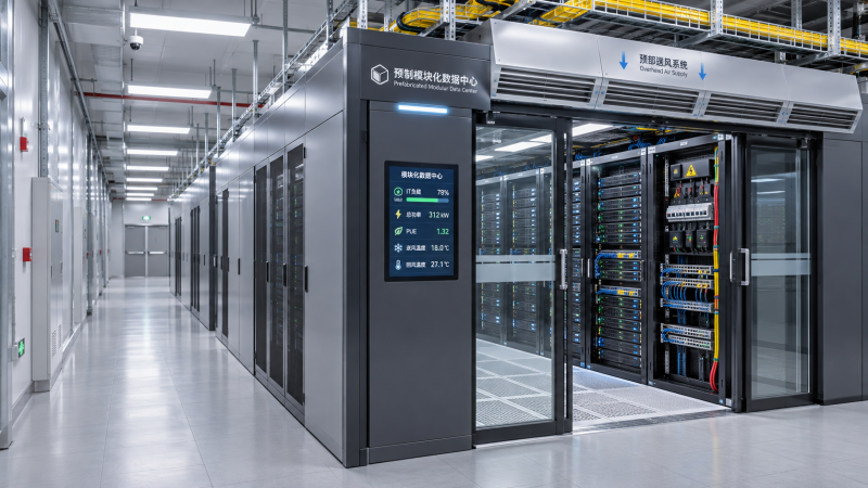
 How to estimate the IT capacity a prefabricated data center needsEstimate prefabricated data center IT capacity with a practical guide to rack density, power, cooling, redundancy, and growth. Compare solutions with confidence.Nov 04, 2026
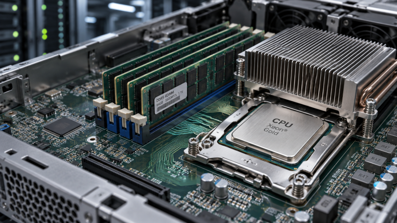
 Server CPUs Explained: Cores, Clock Speed and Memory BandwidthServer CPUs explained: discover how cores, clock speed and memory bandwidth affect performance, and learn how to choose the right processor for your workload.Nov 04, 2026
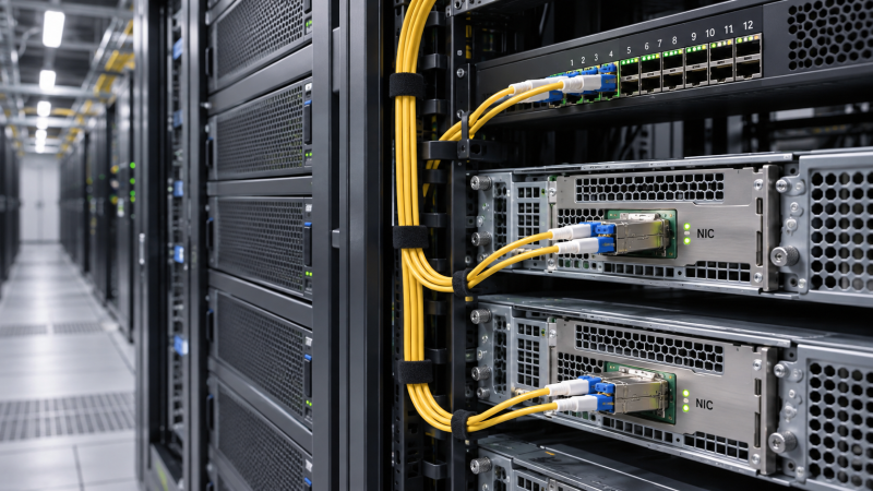
 Network Interface Cards: When Does a Server Need 25GbE or 100GbE?Network Interface Cards: Discover when 25GbE is enough or 100GbE pays off, and check workloads, compatibility and costs before upgrading.Nov 04, 2026
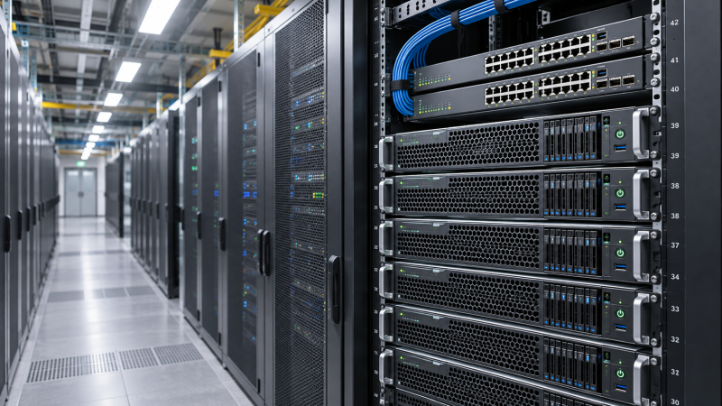
 Rack Servers Explained: How They Fit into Data Center InfrastructureRack servers are key to data center infrastructure. Explore power, cooling, networking, and space requirements to plan a reliable deployment.Nov 04, 2026